Information provided here gives an overview of the security features included on your switch. Access Security and Switch Authentication Features outlines the access security and authentication features, while Network Security—Default Settings and Security Guidelines highlights the additional features designed to help secure and protect your network. For detailed information on individual features, see the references provided.
Before you connect your switch to a network, HP strongly recommends that you review the section titled . It outlines potential threats for unauthorized switch and network access, and provides guidelines on how to prepare the switch for secure network operation.
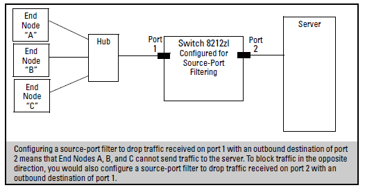
You can enhance in-band security and improve control over access to network resources by configuring static filters to forward (the default action) or drop unwanted traffic. That is, you can configure a traffic filter to either forward or drop all network traffic moving to outbound (destination) ports and trunks (if any) on the switch
As of June 2010, Traffic/Security filers are available on these current HP switch models:
Switch model filter availability
| Model | Source-Port Filters | Protocol Filters | Multicast Filters |
|---|---|---|---|
| 8200zl Switches | Yes | Yes | Yes |
| 6600 Switches | Yes | Yes | Yes |
| 8400cl Switches | Yes | No | No |
| 5400zl Switches | Yes | Yes | Yes |
| 4200vl Switches | Yes | No | No |
| 3800 Switches | Yes | Yes | Yes |
| 3500/3500yl Swtiches | Yes | Yes | Yes |
| 3400cl Switches | Yes | No | No |
| 2800 Switches | Yes | No | No |
| 2510 Switches | Yes | Yes | Yes |
| 2500 Switches | Yes | Yes | Yes |
| 4000m and 8000m Switches | Yes | Yes | Yes |
The switch accepts up to 101 static filters. These limitations apply:
-
Source-port filters: up to 78
-
Multicast filters: up to 16 with 1024 or fewer VLANs configured. Up to 8 with more than 1024 VLANs configured.
-
Protocol filters: up to 7
The switch manages a port trunk as a single source or destination for sourceport filtering. If you configure a port for filtering before adding it to a port trunk, the port retains the filter configuration, but suspends the filtering action while a member of the trunk. If you want a trunk to perform filtering, first configure the trunk, then configure the trunk for filtering. See Configuring a filter on a port trunk.
The following table represents the types of static filters and their selection criteria:
Filter types and criteria
| Static Filter Type | Selection criteria |
|---|---|
| Source-port | Inbound traffic from a designated, physical source-port will be forwarded or dropped on a per-port (destination) basis. |
| Multicast | Inbound traffic having a specified multicast MAC address will be forwarded to outbound ports (the default) or dropped on a per-port (destination) basis. |
| Protocol | Inbound traffic having the selected frame (protocol) type will be forwarded or dropped on a per-port (destination) basis. |
This filter type enables the switch to forward or drop traffic from all end nodes on the indicated source-port to specific destination ports.
-
You can configure one source-port filter for each physical port and port trunk on the switch. (See Defining and configuring named source-port filters.)
-
You can include all destination ports and trunks in the switch on a single source-port filter.
-
Each source-port filter includes:
When you create a source-port filter, the switch automatically sets the filter to forward traffic from the designated source to all destinations for which you do not specifically configure a “drop” action. Thus, it is not necessary to configure a source-port filter for traffic you want the switch to forward unless the filter was previously configured to drop the desired traffic.
-
When you create a source port filter, all ports and port trunks (if any) on the switch appear as destinations on the list for that filter, even if routing is disabled and separate VLANs and subnets exist. Where traffic would normally be allowed between ports and trunks, the switch automatically forwards traffic to the outbound ports and trunks you do not specifically configure to drop traffic. (Destination ports that comprise a trunk are listed collectively by the trunk name— such as Trk1— instead of by individual port name.)
-
Packets allowed for forwarding by a source-port filter are subject to the same operation as inbound packets on a port that is not configured for source-port filtering.
-
With multiple IP addresses configured on a VLAN, and routing enabled on the switch, a single port or trunk can be both the source and destination of packets moving between subnets in that same VLAN. In this case, you can prevent the traffic of one subnet from being routed to another subnet of the same port by configuring the port or trunk as both the source and destination for traffic to drop.
Example
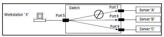
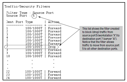
If you wanted to prevent server “A” from receiving traffic sent by workstation “X”, but do not want to prevent any other servers or end nodes from receiving traffic from workstation “X”, you would configure a filter to drop traffic from port 5 to port 7. The resulting filter would drop traffic from port 5 to port 7, but would forward all other traffic from any source port to any destination port. (See Filter blocking traffic only from Port 5 to Server A and Filter for the actions shown in Figure 308.
You can specify named source-port filters that may be used on multiple ports and port trunks. A port or port trunk can only have one source-port filter, but by using this capability you can define a source-port filter once and apply it to multiple ports and port trunks. This can make it easier to configure and manage source-port filters on your switch. The commands to define, configure, apply, and display the status of named source-port filters are described below.
-
A port or port trunk may only have one source-port filter, named or not named.
-
A named source-port filter can be applied to multiple ports or port trunks.
-
Once a named source-port filter is defined, subsequent changes only modify its action, they don’t replace it.
-
To change the named source-port filter used on a port or port trunk, the current filter must first be removed, using the
no filter source-port named-filter <filter-name>command. -
A named source-port filter can only be deleted when it is not applied to any ports.
This filter type enables the switch to forward or drop multicast traffic to a specific set of destination ports. This helps to preserve bandwidth by reducing multicast traffic on ports where it is unnecessary, and to isolate multicast traffic to enhance security.
You can configure up to 16 static multicast filters (defined by the filter command). However, if an IGMP-controlled filter for a joined multicast group has the same multicast address as a static multicast filter configured on a given port, the IGMP-controlled filter overrides the static multicast filter configured on that port. Note that in the default configuration, IGMP is disabled on VLANs configured in the switch. To enable IGMP on a specific VLAN, use the vlan <vid> ip igmp command. (For more on this command, see “Multimedia Traffic Control with IP Multicast (IGMP)” in the Multicast and Routing Guide for your switch.)
The total of static multicast filters and IGMP multicast filters together can range from 389 to 420, depending on the current max-vlans setting in the switch. If multiple VLANs are configured, then each filter is counted once per VLAN in which it is used
Multicast filter limits
| Max-VLANs setting | Max # multicast filters (static and IGMP combined) |
|---|---|
| 1 (minimum) | 420 |
| 8 (default) | 413 |
| 32 or higher | 389 |
|
|
|
![[CAUTION: ]](images/caution.gif) |
CAUTION: If Spanning Tree is enabled, then the MSTP multicast MAC address (0180c2- 000000) should not be filtered. (STP will not operate properly if the MSTP multicast MAC address is filtered.) |
|
|
This filter type enables the switch to forward or drop, on the basis of protocol type, traffic to a specific set of destination ports on the switch. Filtered protocol types include:
Only one filter for a particular protocol type can be configured at any one time. For example, a separate protocol filter can be configured for each of the protocol types listed above, but only one of those can be an IP filter. Also, the destination ports for a protocol filter can be on different VLANs.
The switch automatically assigns each new filter to the lowest-available index (IDX) number. The index numbers are included in the show filter command described in the next section and are used with the show filter <index> command to display detailed information about a specific filter.
If there are no filters currently configured, and you create three filters in succession, they will have index numbers 1 - 3. However, if you then delete the filter using index number “2” and then configure two new filters, the first new filter will receive the index number “2” and the second new filter will receive the index number "4". This is because the index number “2” was made vacant by the earlier deletion, and was therefore the lowest index number available for the next new filter.
-
Once a password has been configured on the switch, you cannot remove it using the CLI wizard. Passwords can be removed by executing the
no passwordcommand directly from the CLI. -
When you restrict SNMP access to SNMPv3 only, the options SNMPv2 community name and access level will not appear.
-
The wizard displays the first available SNMPv2 community and allows the user to modify the first community access parameters.
-
The wizard creates a new SNMP community only when no communities have been configured on the switch.
-
The USB Autorun feature is disabled as soon as an operator or manager password is set on the switch. Once a password has been set, the USB autorun option is no longer provided as part of the wizard.