An Access Control List (ACL) is a list of one or more Access Control Entries (ACEs), where each ACE consists of a matching criteria and an action (permit or deny). The information below describes how to configure, apply, and edit static IPv4 ACLs in a network populated with the switches, and how to monitor IPv4 ACL actions.
IPv4 filtering with ACLs can help improve network performance and restrict network use by creating policies for:
|
Eliminates unwanted traffic in a path by filtering IPv4 packets where they enter or leave the switch on specific VLAN interfaces. |
IPv4 ACLs can filter traffic to or from a host, a group of hosts, or entire subnets.
Interface options
| Interface | ACL application | Application point | Filter action |
|---|---|---|---|
| Port | Static Port ACL (switch configured) | inbound on the switch port | inbound IPv4 traffic |
| RADIUS-Assigned ACL [1] | inbound on the switch port used by authenticated client | inbound IPv4 and IPv6 traffic from the authenticated client | |
| VLAN | VACL | entering the switch on the VLAN | inbound IPv4 traffic |
| RACL[2] | entering the switch on the VLAN | routed IPv4 traffic entering the switch and any IPv4 traffic with a destination on the switch itself | |
| exiting from the switch on the VLAN | routed IPv4 traffic exiting from the switch | ||
|
[1] The information provided here describes ACLs statically configured on the switch. See RADIUS services supported on HPE switches. [2] Supports one inbound and one outbound RACL. When both are used, one RACL can be assigned to filter both inbound and outbound, or different RACLs can be assigned to filter inbound and outbound. |
|||
-
ACLs do not provide DNS hostname support. ACLs cannot be configured to screen hostname IPv4 traffic between the switch and a DNS.
-
ACLs Do Not Affect Serial Port Access. ACLs do not apply to the switch’s serial port.
-
ACL Screening of IPv4 Traffic Generated by the Switch. Outbound RACL applications on a switch do not screen IPv4 traffic generated by the switch itself (such as broadcasts, Telnet, Ping, and ICMP replies). Note that ACLs applied on the switch do screen this type of IPv4 traffic when other devices generate it. Similarly, ACL applications can screen responses from other devices to unscreened IPv4 traffic the switch generates.
-
-
The ACL logging feature generates a message only when packets are explicitly denied or permitted as the result of a match, and not when implicitly denied. To help test ACL logging, configure the last entry in an ACL as an explicit deny or permit statement with a log statement included, and apply the ACL to an appropriate VLAN.
-
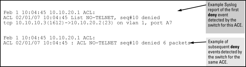
A detailed event is logged for the first packet that matches a “deny” or “permit” ACL logged entry with the appropriate action specified. Subsequent packets matching ACL logged entries generate a new event that summarizes the number of packets that matched each specific entry (with the time period).
-
Logging enables you to selectively test specific devices or groups. However, excessive logging can affect switch performance. For this reason, Hewlett Packard Enterprise recommends that you remove the logging option from ACEs for which you do not have a present need. Also, avoid configuring logging where it does not serve an immediate purpose. (Note that ACL logging is not designed to function as an accounting method.) See also “Apparent Failure To Log All ‘Deny’ or ‘Permit’ Matches” in the section titled “ACL Problems”, found in appendix C, “Troubleshooting” of the management and configuration guide for your switch.
-
When configuring logging, you can reduce excessive resource use by configuring the appropriate ACEs to match with specific hosts instead of entire subnets.
-
-
Minimum Number of ACEs in an ACL. Any ACL must include at least one ACE to enable IP traffic screening. A numbered ACL cannot be created without at least one ACE. A named ACL can be created “empty”; that is, without any ACEs. However in an empty ACL applied to an interface, the Implicit Deny function does not operate, and the ACL has no effect on traffic.
-
Monitoring Shared Resources. Applied ACLs share internal switch resources with several other features. The switch provides ample resources for all features. However, if the internal resources become fully subscribed, additional ACLs cannot be applied until the necessary resources are released from other applications. For information on determining current resource availability and usage, see Appendix E, “Monitoring Resources” in the management and configuration guide for your switch.
-
Protocol Support . ACL criteria does not include use of MAC information or QoS.
-
Replacing or Adding To an Active ACL Policy. If you assign an ACL to an interface and subsequently add or replace ACEs in that ACL, each new ACE becomes active when you enter it. If the ACL is configured on multiple interfaces when the change occurs, then the switch resources must accommodate all applications of the ACL. If there are insufficient resources to accommodate one of several ACL applications affected by the change, then the change is not applied to any of the interfaces and the previous version of the ACL remains in effect.
-
“Strict” TCP and UDP. When the ACL configuration includes TCP or UDP options, the switch operates in “strict” TCP and UDP mode for increased control. In this case, the switch compares all TCP and UDP packets against the ACLs. (In the 9300m and 9404sl Routing Switches, the Strict TCP and Strict UDP modes are optional and must be specifically invoked.)
An ACL is a list of one or more Access Control Entries (ACEs), where each ACE consists of a matching criteria and an action (permit or deny). A static ACL applies only to the switch in which it is configured. ACLs operate on assigned interfaces, and offer these traffic filtering options:
-
IPv4 traffic inbound on a port.
-
IPv4 traffic inbound on a VLAN.
-
Routed IPv4 traffic entering or leaving the switch on a VLAN. (Note that ACLs do not screen traffic at the internal point where traffic moves between VLANs or subnets within the switch. See ACL applications.
The following table lists the range of interface options:
Range of interface options
| Interface | ACL Application | Application Point | Filter Action |
|---|---|---|---|
| Port | Static Port ACL (switch configured) | inbound on the switch | inbound IPv4 traffic |
| RADIUS-Assigned ACL[a] | inbound on the switch port used by authenticated client | inbound IPv4 and IPv6 traffic from the authenticated client | |
| VLAN | VACL | entering the switch on the VLAN | inbound IPv4 traffic |
| RACL[b] | entering the switch on the VLAN | routed IPv4 traffic entering the switch and any IPv4 traffic with a destination on the switch itself | |
| exiting from the switch on the VLAN | routed IPv4 traffic exiting from the switch | ||
|
[a] The information provided here describes ACLs statically configured on the switch. For information on RADIUSassigned ACLs, see RADIUS services supported on HPE switches. [b] Supports one inbound and one outbound RACL. When both are used, one RACL can be assigned to filter both inbound and outbound, or different RACLs can be assigned to filter inbound and outbound. |
|||
|
|
|
![[NOTE: ]](images/note.gif) |
NOTE: After you assign an IPv4 ACL to an interface, the default action on the interface is to implicitly deny IPv4 traffic that is not specifically permitted by the ACL. (This applies only in the direction of traffic flow filtered by the ACL.) |
|
|
To apply IPv4 ACL filtering, assign a configured IPv4 ACL to the interface on which you want traffic filtering to occur. VLAN and routed IPv4 traffic ACLs can be applied statically using the switch configuration. Port traffic ACLs can be applied either statically or dynamically (using a RADIUS server).
Static ACLs are configured on the switch. To apply a static ACL, you must assign it to an interface (VLAN or port). The switch supports three static ACL applications:
An RACL is an ACL configured on a VLAN to filter routed traffic entering or leaving the switch on that interface, as well as traffic having a destination on the switch itself. (Except for filtering traffic to an address on the switch itself, RACLs can operate only while IPv4 routing is enabled.
A VACL is an ACL configured on a VLAN to filter traffic entering the switch on that VLAN interface and having a destination on the same VLAN.
A static port ACL is an ACL configured on a port to filter traffic entering the switch on that port, regardless of whether the traffic is routed, switched, or addressed to a destination on the switch itself.
A RADIUS-assigned ACL is configured on a RADIUS server for assignment to a given port when the server authenticates a specific client on that port. When the server authenticates a client associated with that ACL, the ACL is assigned to the port the client is using. The ACL then filters the IP traffic received inbound on that port from the authenticated client. If the RADIUS server supports both IPv4 and IPv6 ACEs, then the ACL assigned by the server can be used to filter both traffic types, or filter IPv4 traffic and drop IPv6 traffic. When the client session ends, the ACL is removed from the port. The switch allows as many RADIUS-assigned ACLs on a port as it allows authenticated clients. For information on RADIUS-assigned ACLs assigned by a RADIUS server, see RADIUS services supported on HPE switches.
A permit or deny policy for IPv4 traffic you want to filter can be based on source address alone, or on source address plus other factors.
Use a standard ACL when you need to permit or deny IPv4 traffic based on source address only. Standard ACLs are also useful when you need to quickly control a performance problem by limiting IPv4 traffic from a subnet, group of devices, or a single device. This can block all IPv4 traffic from the configured source, but does not hamper IPv4 traffic from other sources within the network.
A standard ACL uses an alphanumeric ID string or a numeric ID of 1 through 99. Specify a single host, a finite group of hosts, or any host.
A named, standard ACL is identified by an alphanumeric string of up to 64 characters and is created by entering the Named ACL (nacl) context.
A numbered, standard ACL is identified by a number in the range of 1 - 99 and is created without having to leave the global config context. Note that the CLI command syntax for creating a named ACL differs from the command syntax for creating a numbered ACL.
For example, the first pair of entries below illustrate how to create (or enter) a named, standard ACL and enter an ACE. The next entry illustrates creating a numbered, standard ACL with the same ACE.
switch(config)# ip access-list standard Test-List
switch(config-std-nacl)# permit host 10.10.10.147
switch(config)# access-list 1 permit host 10.10.10.147
Once a numbered ACL has been created, it can be accessed using the named ACL method. This is useful if it becomes necessary to edit a numbered ACL by inserting or removing individual ACEs. (Inserting or deleting an ACE is done by sequence number, and requires the Named ACL (nacl) context.) The switch allows a maximum of 2048 unique ACL identities (IPv4 and IPv6 combined). See Monitoring shared resources.
|
|
|
|
|
NOTE: See Configuring standard ACLs for a summary of standard ACL commands. For a summary of all IPv4 ACL commands, see IPv4 Access Control Lists (ACLs). |
|
|
Use an extended ACL when simple IPv4 source address restrictions do not provide the sufficient traffic selection criteria needed on an interface. Extended ACLs allow use of the following criteria:
-
source and destination IPv4 address combinations
-
IPv4 protocol options
Extended, named ACLs also offer an option to permit or deny IPv4 connections using TCP for applications such as Telnet, http, ftp, and others.
An optional feature used with Connection-Rate filtering based on virus-throttling technology. See Virus throttling (connection-rate filtering).
ACL filtering is applied to IPv4 traffic as follows:
|
Routed ACL (RACL) |
on a VLAN configured with an RACL:
|
|
VLAN ACL (VACL) |
on a VLAN configured with a VACL, inbound IP traffic, regardless of whether it is switched or routed. On a multinet VLAN, this includes inbound IPv4 traffic from any subnet. |
|
Static port ACL |
any inbound IPv4 traffic on that port. |
|
RADIUS-assigned ACL |
on a port having an ACL assigned by a RADIUS server to filter an authenticated client's traffic, filters inbound IPv4 and IPv6 traffic from that client For information on RADIUS-assigned ACLs, see RADIUS services supported on HPE switches. |
Beginning with software release K.14.01, ACL mirroring per VLAN, port, and trunk interfaces is deprecated in favor of a classifier-based rate-limiting feature that does not use ACLs. If ACL mirroring is already configured in a switch running software version K.13.xx, then downloading and booting from release K.14.01 or greater automatically modifies the deprecated configuration to conform to the classifier-based rate-limiting supported in release K.14.01 or greater. For more information on this topic, see “Classifier-Based Software Configuration” in the latest advanced traffic management guide for your switch.
|
An optional feature used with Connection-Rate filtering based on virus-throttling technology. See Virus throttling (connection-rate filtering). |
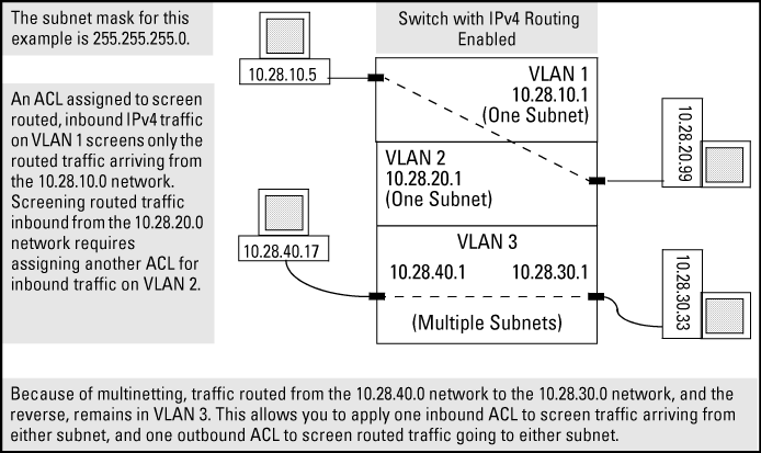
RACLs filter routed IPv4 traffic entering or leaving the switch on VLANs configured with the "in" and "out" ACL option
Syntax
For example, in RACL filter applications on routed IPv4 traffic:
-
Assign either an inbound ACL on VLAN 1 or an outbound ACL on VLAN 2 to filter a packet routed between subnets on different VLANs; that is, from the workstation 10.28.10.5 on VLAN 1 to the server at 10.28.20.99 on VLAN 2. An outbound ACL on VLAN 1 or an inbound ACL on VLAN 2 would not filter the packet.
-
Where multiple subnets are configured on the same VLAN, use either inbound or outbound ACLs to filter routed IPv4 traffic between the subnets on the VLAN. Traffic source and destination IP addresses must be on devices external to the switch.
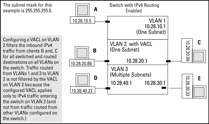
VACLs filter any IPv4 traffic entering the switch on a VLAN configured with the "VLAN" ACL option.
Syntax
For example, in VACL filter application to IPv4 traffic entering the switch, you would assign a VACL to VLAN 2 to filter all inbound switched or routed IPv4 traffic received from clients on the 10.28.20.0 network. In this instance, routed traffic received on VLAN 2 from VLANs 1 or 3 would not be filtered by the VACL on VLAN 2.
|
|
|
|
|
NOTE: The switch allows one VACL assignment configured per VLAN. This is in addition to any other ACL applications assigned to the VLAN or to ports in the VLAN. |
|
|
An IPv4 static port ACL filters any IPv4 traffic inbound on the designated port, regardless of whether the traffic is switched or routed.
|
|
|
|
|
NOTE: Beginning with software release K.14.01, IPv6 support is available for RADIUS-assigned port ACLs configured to filter inbound IPv4 and IPv6 traffic from an authenticated client. Also, the implicit deny in RADIUS-assigned ACLs applies to both IPv4 and IPv6 traffic inbound from the client. For information on enabling RADIUS-assigned ACLs, see RADIUS services supported on HPE switches. |
|
|
Dynamic (RADIUS-assigned) port ACLs are configured on RADIUS servers and can be configured to filter IPv4 and IPv6 traffic inbound from clients authenticated by such servers.
User-Based 802.1X access control allows up to 32 individually authenticated clients on a given port. Port-Based access control does not set a client limit, and requires only one authenticated client to open a given port, and is recommended for applications where only one client at a time can connect to the port.
-
If you configure 802.1X user-based security on a port and the RADIUS response includes a RADIUS-assigned ACL for at least one authenticated client, then the RADIUS response for all other clients authenticated on the port must also include a RADIUS-assigned ACL. Inbound IP traffic on the port from a client that authenticates without receiving a RADIUS-assigned ACL is dropped and the client is de-authenticated.
-
Using 802.1X port-based security on a port where the RADIUS response to a client authenticating includes a RADIUS-assigned ACL, different results can occur, depending on whether any additional clients attempt to use the port and whether these other clients initiate an authentication attempt. This option is recommended for applications where only one client at a time can connect to the port, and not recommended for instances where multiple clients may access the same port at the same time. For more information, see 802.1X Port-based access control.
-
For RADIUS ACL applications using software release K.14.01 or greater, the switch operates in a dual-stack mode, and a RADIUS-assigned ACL can filter both IPv4 and IPv6 traffic. At a minimum, a RADIUS-assigned ACL automatically includes the implicit deny for both IPv4 and IPv6 traffic. Thus, an ACL configured on a RADIUS server to filter IPv4 traffic also denies inbound IPv6 traffic from an authenticated client unless the ACL includes ACEs that permit the desired IPv6 traffic. The reverse is true for a dynamic ACL configured on RADIUS server to filter IPv6 traffic. (ACLs are based on the MAC address of the authenticating client.) See RADIUS services supported on HPE switches.
-
To support authentication of IPv6 clients:
-
The VLAN to which the port belongs must be configured with an IPv6 address.
-
Connection to an IPv6-capable RADIUS server must be supported.
-
For 802.1X or MAC authentication methods, clients can authenticate regardless of their IP version (IPv4 or IPv6).
-
For the Web authentication method, clients must authenticate using IPv4. However, this does not prevent the client from using adual stack, or the port receiving a RADIUS-assigned ACL configured with ACEs to filter IPv6 traffic.
-
The RADIUS server must support IPv4 and have an IPv4 address. (RADIUS clients can be dual stack, IPv6 only, or IPv4 only.)
-
802.1X rules for client access apply to both IPv6 and IPv4 clients for RADIUS-assigned ACLs. See 802.1X User-Based and Port-Based applications.
-
The switch allows multiple ACL applications on an interface (subject to internal resource availability). This means that a port belonging to a given VLAN "X" can simultaneously be subject to all of the following:
Per-interface multiple ACL assignments
| ACL type | ACL application |
|---|---|
| Dynamic (RADIUS-assigned) ACLs |
One port-based ACL (for first client to authenticate on the port) or up to 32 user-based ACLs (one per authenticated client) Note: If one or more user-based, dynamic ACLs are assigned to a port, then the only traffic allowed inbound on the port is from authenticated clients. |
| IPv6 static ACLs: | One static VACL for IPv6 traffic for VLAN "X" entering the switch through the port.
One static port ACL for IPv6 traffic entering the switch on the port. One inbound and one outbound RACL filtering routed IPv6 traffic moving through the port for VLAN "X". (Also applies to inbound, switched traffic on VLAN "X" that has a destination on the switch itself. |
| IPv4 static ACLs: | One static VACL for IPv4 traffic for VLAN "X" entering the switch through the port. |
| One static port ACL for any IPv4 traffic entering the switch on the port | |
| One connection-rate ACL for inbound IPv4 traffic for VLAN "X" on the port (if the port is configured for connection-rate filtering). See Virus throttling (connection-rate filtering). | |
| One inbound and one outbound RACL filtering routed IPv4 traffic moving through the port for VLAN "X". This also applies to inbound, switched traffic on VLAN "X" that has a destination on the switch itself. |
On a given interface where multiple ACLs apply to the same traffic, a packet having a match with a deny ACE in any applicable ACL on the interface (including an implicit deny any)is dropped.
For example, suppose the following is true:
-
Port A10 belongs to VLAN 100.
-
A static port ACL is configured on port A10.
-
A VACL is configured on VLAN 100.
-
An RACL is also configured for inbound, routed traffic on VLAN 100.
An inbound, switched packet entering on port A10, with a destination on port A12, is screened by the static port ACL and the VACL, regardless of a match with any permit or deny action. A match with a deny action (including an implicit deny) in either ACL causes the switch to drop the packet. (If the packet has a match with explicit deny ACEs in multiple ACLs and the log option is included in these ACEs, then a separate log event occurs for each match.) The switched packet is not screened by the RACL.
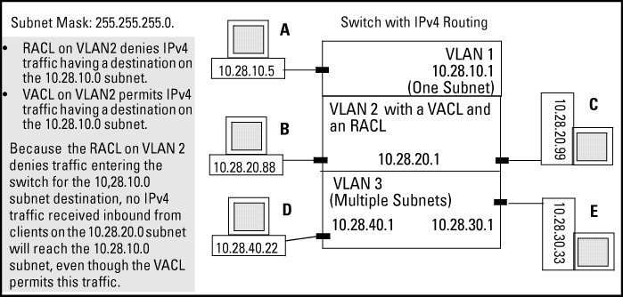
However, suppose that VLAN 2 in Order of application for multiple ACLs on an interface is configured with the following:
-
A VACL permitting traffic having a destination on the 10.28.10.0 subnet
-
An RACL that denies inbound traffic having a destination on the 10.28.10.0 subnet
In this case, no IPv4 traffic received on the switch from clients on the 10.28.20.0 subnet reaches the 10.28.10.0 subnet, even though the VACL allows such traffic. This is because the deny in the RACL causes the switch to drop the traffic regardless of whether any other VACLs permit the traffic.
Connection-rate filtering can be configured along with one or more other ACL applications on the same interface. In this case, a connection-rate match for a filter action is carried out according to the configured policy, regardless of whether any other ACLs on the interface have a match for a deny action. Also, if a connection-rate filter permits (ignore action) a packet, it can still be denied by another ACL on the interface.
-
All ACEs in an ACL configured on the switch are automatically sequenced (numbered). For an existing ACL, entering an ACE without specifying a sequence number automatically places the ACE at the end of the list. Specifying a sequence number inserts the ACE into the list at the specified sequential location.
-
A source or destination IPv4 address and amask, together, can define a single host, a range of hosts, or all hosts.
-
Every ACL populated with one or more explicit ACEs includes an Implicit Deny as the last entry in the list. The switch applies this action to any packets that do not match other criteria in the ACL. For standard ACLs, the Implicit Deny is
deny any. For extended ACLs, it isdeny ip any any. -
In any ACL, you can apply an ACL log function to ACEs that have an explicit "deny" action. The logging occurs when there is a match on a "deny" ACE. The switch sends ACL logging output to Syslog, if configured, and, optionally, to a console session.
You can create ACLs for the switch configuration using either the CLI or a text editor. The text-editor method is recommended when you plan to create or modify an ACL that has more entries than you can easily enter or edit using the CLI alone. See Enabling ACL logging on the switch.
-
Identify the ACL action to apply. As part of this step, determine the best points at which to apply specific ACL controls. For example, you can improve network performance by filtering unwanted IPv4 traffic at the edge of the network instead of in the core. Also, on the switch itself, you can improve performance by filtering unwanted IPv4 traffic where it is inbound to the switch instead of outbound.
Traffic source ACL application IPv4 or IPv6 traffic from a specific, authenticated client RADIUS-assigned ACL for inbound IP traffic from an authenticated client on a port[a] IPv4 traffic entering the switch on a specific port static port ACL (static-port assigned) for any inbound IPv4 traffic on a port from any source switched or routed IPv4 traffic entering the switch on a specific VLAN VACL (VLAN ACL) routed IPv4 traffic entering or leaving the switch on a specific VLAN RACL (routed ACL) [a] For more on this option, see RADIUS services supported on HPE switches, and see also the documentation for your RADIUS server.
-
Identify the traffic types to filter. (IPv4 only, unless the ACL is a RADIUS-assigned ACL, which supports IPv4 and IPv6 filtering.
-
The SA and the DA of traffic you want to permit or deny. This can be a single host, a group of hosts, a subnet, or all hosts.
-
Any TCP traffic (only) for a specific TCP port or range of ports, including optional control of connection traffic based on whether the initial request should be allowed
-
All ICMP traffic or ICMP traffic of a specific type and code
-
-
Design the ACLs for the control points (interfaces) selected. When using explicit "deny" ACEs, optionally use the VACL logging feature for notification that the switch is denying unwanted packets.
-
Assign the ACLs to the interfaces you want to filter, using the ACL application (static port ACL, VACL, or RACL) appropriate for each assignment.
-
If using an RACL, ensure thatIPv4 routing is enabled on the switch.
For more details on ACL planning considerations, see Configuring named, standard ACLs.
|
|
|
|
|
NOTE: To activate a RACL to screen inbound IPv4 traffic for routing between subnets, assign the RACL to the statically configured VLAN on which the traffic enters the switch. Also, ensure that IPv4 routing is enabled. Similarly, to activate a RACL to screen routed, outbound IPv4 traffic, assign the RACL to the statically configured VLAN on which the traffic exits from the switch. A RACL configured to screen inbound IPv4 traffic with a destination address on the switch itself does not require routing to be enabled. (ACLs do not screen outbound IPv4 traffic generated by the switch, itself.) |
|
|
![[CAUTION: ]](images/caution.gif)
When an ACL filters a packet, it sequentially compares each ACE's filtering criteria to the corresponding data in the packet until it finds a match. The action indicated by the matching ACE (deny or permit) is then performed on the packet.
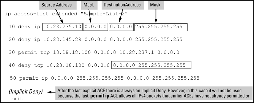
If a packet does not have a match with the criteria in any of the ACEs in the ACL, the ACL denies (drops) the packet. If you need to override the implicit deny so that a packet that does not have a match is permitted, then you can use the "permit any" option as the last ACE in the ACL. This directs the ACL to permit (forward) packets that do not have a match with any earlier ACE listed in the ACL, and prevents these packets from being filtered by the implicit "deny any".
Suppose the ACL in the following figure is assigned to filter the IPv4 traffic from an authenticated client on a given port in the switch:
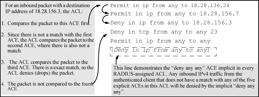
As shown above, the ACL tries to apply the first ACE in the list. If there is no match it tries the second ACE, and so on. When a match is found, the ACL invokes the configured action for that entry (permit or drop the packet) and no further comparisons of the packet are made with the remaining ACEs in the list.
This means that when an ACE whose criteria matches a packet is found, the action configured for that ACE is invoked, and any remaining ACEs in the ACL are ignored.Because of this sequential processing, successfully implementing an ACL depends in part on configuring ACEs in the correct order for the overall policy you want the ACL to enforce.

For example, suppose you want to configure an ACL on the switch (with an ID of "Test-02") to invoke these policies for routed traffic entering the switch on VLAN 12:
The following ACL model , when assigned to inbound filtering on an interface, supports the above case:
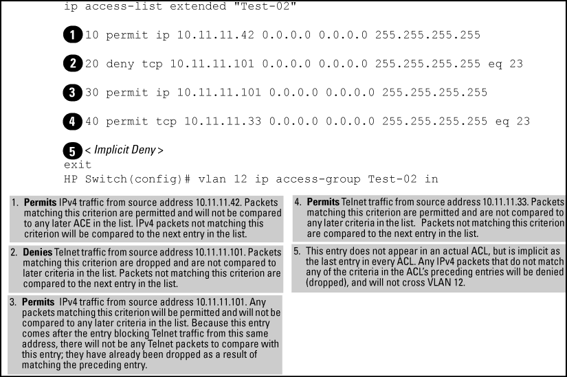
It is important to remember that all IPv4 ACLs configurable on the switch include an implicit deny ip any. That is, IPv4 packets that the ACL does not explicitly permit or deny is implicitly denied, and therefore dropped instead of forwarded on the interface. If you want topreempt the implicit deny so that IPv4 packets not explicitly denied by other ACEs in the ACL are permitted, insert an explicit "permit any" as the last ACE in the ACL. Doing so permits any packet not explicitly denied by earlier entries.
|
|
|
|
|
NOTE: This solution does not apply in the preceding example, where the intention is for the switch to forward only explicitly permitted IPv4 packets routed on VLAN 12. |
|
|
-
The
resequencecommand ignores "orphan" remarks that do not have an ACE counterpart with the same sequence number. For example, if:then the remark retains "55" as its sequence number and is placed in the renumbered version of the ACL according to that sequence number.
-
Entering an unnumbered remark followed by a numbered ACE, or the reverse, creates an "orphan" remark. The unnumbered entry is assigned a sequence number that is an increment from the last ACE in the list. The numbered entry is then placed sequentially in the list according to the sequence number used.
-
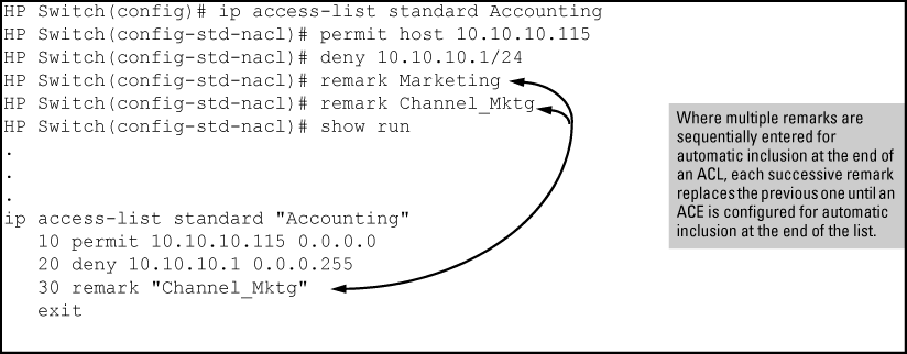
Configuring two remarks without either sequence numbers or an intervening, unnumbered ACE results in the second remark overwriting the first.
Before creating and implementing ACLs, you need todefine the policies you want your ACLs to enforce, and understand how the ACL assignments impact your network users.
|
|
|
|
|
NOTE: All IPv4 traffic entering the switch on a given interface is filtered by all ACLs configured for inbound traffic on that interface. For this reason, an inbound IPv4 packet is denied (dropped) if it has a match with either an implicit or explicit See Multiple ACLs on an interface for more detail. |
|
|
Use ACLs to block traffic from individual hosts, workgroups, or subnets, and to block access to VLANs, subnets, devices, and services.
Traffic criteria for ACLs include:
-
Switched and routed traffic
-
Any traffic of a specific IPv4 protocol type (0-255)
-
Any TCP traffic (only) for a specific TCP port or range of ports, including optional control of connection traffic based on whether the initial request should be allowed
-
Any UDP traffic or UDP traffic for a specific UDP port
-
Any ICMP traffic or ICMP traffic of a specific type and code
-
Any IGMP traffic or IGMP traffic of a specific type
-
Any of the above with specific precedence and ToS settings
Depending on the source and destination of a given IPv4 traffic type, you must also determine the ACL application (RACL, VACL, or static port ACL) needed to filter the traffic on the applicable switch interfaces. Answering the following questions can help you to design and properly position IPv4 ACLs for optimum network usage.
-
What are the logical points for minimizing unwanted traffic, and what ACL applications should be used? In many cases it makes sense to prevent unwanted traffic from reaching the core of your network by configuring ACLs to drop the unwanted traffic at or close to the edge of the network. The earlier in the network path you can block unwanted traffic, the greater the benefit for network performance.
-
From where is the traffic coming? The source and destination of traffic you want to filter determines the ACL application to use (RACL, VACL, static port ACL, and RADIUS-assigned ACL).
-
What traffic should you explicitly block? Depending on your network size and the access requirements of individual hosts, this can involve creating a large number of ACEs in a given ACL (or a large number of ACLs), which increases the complexity of your solution.
-
What traffic can you implicitly block by taking advantage of the implicit deny ip any to deny traffic that you have not explicitly permitted? This can reduce the number of entries needed in an ACL.
-
What traffic should you permit? In some cases you need to explicitly identify permitted traffic. In other cases, depending on your policies, you can insert an ACE with "permit any" forwarding at the end of an ACL. This means that all IPv4 traffic not specifically matched by earlier entries in the list is permitted.
ACLs can enhance security by blocking traffic carrying an unauthorized source IPv4 address (SA). This can include:
-
Blocking access from specific devices or interfaces (port or VLAN)
-
Blocking access to or from subnets in your network
-
Blocking access to or from the internet
-
Blocking access to sensitive data storage or restricted equipment
-
Preventing specific IPv4, TCP, UDP, IGMP, and ICMP traffic types, including unauthorized access using functions such as Telnet, SSH, and web browser
You can also enhance switch management security by using ACLs to block IPv4 traffic that has the switch itself as the destination address (DA).
After determining the filtering type (standard or extended) and ACL application (RACL, VACL, or static port ACL) to use at a particular point in your network, determine the order in which to apply individual ACEs to filter IPv4 traffic For information on ACL applications, see ACL applications.
-
The sequence of ACEs is significant. When the switch uses an ACL to determine whether to permit or deny a packet on a particular VLAN, it compares the packet to the criteria specified in the individual Access Control Entries (ACEs) in the ACL, beginning with the first ACE in the list and proceeding sequentially until a match is found. When a match is found, the switch applies the indicated action (permit or deny) to the packet.
-
The first match in an ACL dictates the action on a packet. Subsequent matches in the same ACL areignored.However, if a packet is permitted by one ACL assigned to an interface, but denied by another ACL assigned to the same interface, the packet is denied on the interface.
-
On any ACL, the switch implicitly denies IPv4 packets that are not explicitly permitted or denied by the ACEs configured in the ACL. If you want the switch to forward a packet for which there is not a match in an ACL, append an ACE that enables Permit Any forwarding as the last ACE in the ACL. This ensures that no packets reach the Implicit Deny case for that ACL.
-
Generally, you should list ACEs from the most specific (individual hosts) to the most general (subnets or groups of subnets) unless doing so permits traffic that you want dropped. For example, an ACE allowing a small group of workstations to use a specialized printer should occur earlier in an ACL than an entry used to block widespread access to the same printer.
A standard ACL uses only source IPv4 addresses in its ACEs. This type of ACE is useful when you need to:
-
Permit or deny any IPv4 traffic based on source address only.
-
Quickly control the IPv4 traffic from a specific address. This allows you to isolate IPv4 traffic problems generated by a specific device, group of devices, or a subnet threatening to degrade network performance. This gives you an opportunity to troubleshoot without sacrificing performance for users outside of the problem area.
A named, standard ACL is identified by an alphanumeric string of up to 64 characters and is created by entering the Named ACL (nacl) context. A numbered, standard ACL is identified by a number in the range of 1 - 99 and is created without having to leave the global config context. Note that the CLI command syntax for creating a named ACL differs from the command syntax for creating a numbered ACL. For example, the first pair of entries below illustrate how to create (or enter) a named, standard ACL and enter an ACE. The next entry illustrates creating a numbered, standard ACL with the same ACE.
switch(config)# ip access-list standard Test-List
switch(config-std-nacl)# permit host 10.10.10.147
switch(config)# access-list 1 permit host 10.10.10.147
Note that once a numbered ACL has been created, it can be accessed using the named ACL method. This is useful if it becomes necessary to edit a numbered ACL by inserting or removing individual ACEs. Inserting or deleting an ACE is done by sequence number, and requires the Named ACL (nacl) context. The switch allows a maximum of 2048 unique ACL identities (IPv4 and IPv6 combined). For more on this topic, see Monitoring shared resources.
The CLI provides the capability for editing in the switch by using sequence numbers to insert or delete individual ACEs. An offline method is also available. This section describes using the CLI for editing ACLs. To use the offline method for editing ACLs, see Enabling ACL logging on the switch.
You can use the CLI to delete individual ACEs from anywhere in an ACL, append new ACEs to the end of an ACL, and insert new ACEs anywhere within an ACL.
-
-
When you enter a new ACE in a named ACL without specifying a sequence number, the switch inserts the ACE as the last entry in the ACL.
-
When you enter a new ACE in a named ACL and include a sequence number, the switch inserts the ACE according to the position of the sequence number in the current list of ACEs.
-
-
access-list<1 - 99|100 - 199>command to create or add ACEs to a numbered ACL, each new ACE you enter is added to the end of the current list. (This command does not offer a
<seq-#>option for including a sequence number to enable inserting an ACE at other points in the list.) Note, however, that once a numbered list has been created, you have the option of accessing it in the same way as a named list by using theip access-list<standard|extended>command. This enables you to edit a numbered list in the same way that you would edit a named list. (See the next item in this list.)
-
You can delete any ACE from any ACL (named or numbered) by using the
ip access-listcommand to enter the ACL's context, and then using theno <seq-#>command, see Deleting an ACE from an existing ACL. -
Deleting the last ACE from an ACL leaves the ACL in memory. In this case, the ACL is "empty" and cannot perform any filtering tasks. (In any ACL the Implicit Deny does not apply unless the ACL includes at least one explicit ACE.)
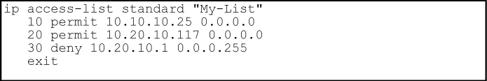
The ACEs in any ACL are sequentially numbered. In the default state, the sequence number of the first ACE in a list is "10" and subsequent ACEs are numbered in increments of 10. For example, the following show run output lists three ACEs with default numbering in a list named "My-List":

You can add an ACE to the end of a named or numbered ACL by using either access-listfor numbered ACLs or ip access-list for named ACLs:

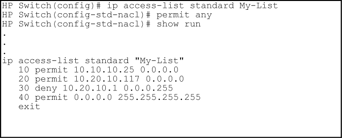
For example, to append a fourth ACE to the end of the ACL:
|
|
|
|
|
NOTE: When using the
ip access-list command to open it as a named ACL and specify a nondefault sequence number, as described in the next section. |
|
|
|
Except for any IPv4 traffic with a DA on the switch itself, RACLs filter only routed IPv4 traffic that is entering or leaving the switch on a given VLAN. Thus, if routing is not enabled on the switch, there is no routed traffic for RACLs to filter. For more on routing, see the latest multicast and routing guide for your switch. |
|
|
A VACL filters traffic entering the switch on the VLANs to which it is assigned. |
|
|
A static port ACL filters traffic entering the switch on the ports or trunks to which it is assigned. |
|
|
At a minimum an ACL must have one, explicit "permit" or "deny" Access Control Entry. You can configure up to 2048 IPv4ACLs each for IPv4 and IPv6. The maximums are as follows:
|
|
|
In any static IPv4 ACL, the switch automatically applies an implicit |
|
|
Entering a |
|
|
Entering a |
|
|
For a specific interface, the most recent ACL assignment using a given application replaces any previous ACL assignment using the same application on the same interface. For example, configuring an RACL named "100" to filter inbound routed traffic on VLAN 20, but later, you configured another RACL named 112 to filter inbound routed traffic on this same VLAN, RACL 112 replaces RACL 100 as the ACL to use. |
|
|
These are applied per-port, per port-list, or per static trunk. Adding a port to a trunk applies the trunk's ACL configuration to the new member. If a port is configured with an ACL, the ACL must be removed before the port is added to the trunk. Also, removing a port from an ACL-configured trunk removes the ACL configuration from that port. |
|
|
These filter any IPv4 traffic entering the switch through any port belonging to the designated VLAN. VACLs do not filter traffic leaving the switch or being routed from another VLAN. |
|
|
You can assign an ACL to any VLAN that is statically configured on the switch. ACLs do not operate with dynamic VLANs. |
|
|
A VACL or RACL assigned to a VLAN applies to all physical ports on the switch belonging to that VLAN, including ports that have dynamically joined the VLAN. |
|
|
RACLs screen routed IPv4 traffic entering or leaving the switch on a given VLAN interface: |
This means that the following traffic is subject to ACL filtering: Filtering the desired, routed traffic requires assigning an RACL to screen traffic inbound or outbound on the appropriate VLANs. In the case of a multinet VLAN, it means that IPv4 traffic inbound from different subnets in the same VLAN is screened by the same inbound RACL, and IPv4 traffic outbound from different subnets is screened by the same outbound RACL. See RACL filter applications on routed IPv4 traffic. |
|
RACLs do not filter switched IPv4 traffic unless the switch itself is the SA or DA |
RACLs do not filter traffic moving between ports belonging to the same VLAN or subnet. (IPv4 traffic moving between ports in different subnets of the same VLAN can be filtered.) |
When the switch applies an ACL to IPv4 traffic, each ACE in the ACL uses an IPv4 address and ACL mask to enforce a selection policy on the packets being screened. That is, the mask determines the range of IPv4 addresses (SA only or SA/DA) that constitute a match between the policy and a packet being screened.
In common IPv4 addressing, a network (or subnet) mask defines which part of the address to use for the network number and which part to use for the hosts on the network. For example:
| Address | Mask | Network address | Host address |
|---|---|---|---|
| 10.38.252.195 | 255.255.255.0 | first three octets | The fourth octet. |
| 10.38.252.195 | 255.255.248.0 | first two octets and the left- most five bits of the third octet | The right most three bits of the third octet and all bits in the fourth octet. |
Thus, the bits set to 1 in a network mask define the part of an IPv4 address to use for the network number, and the bits set to 0 in the mask define the part of the address to use for the host number.
In an ACL, IPv4 addresses and masks provide criteria for determining whether to deny or permit a packet, or to pass it to the next ACE in the list. If there is a match, the configured deny or permit action occurs. If there is not a match, the packet is compared with the next ACE in the ACL. Thus, where a standard network mask defines how to identify the network and host numbers in an IPv4 address, the mask used with ACEs defines which bits in a packet's SA or DA must match the corresponding bits in the SA or DA listed in an ACE, and which bits can be wildcards.
-
For a given ACE, when the switch compares an IPv4 address and corresponding mask in the ACE to an IPv4 address carried in a packet:
-
A mask-bit setting of 0 ("off") requires that the corresponding bits in the packet's address and in the ACE's address must be the same. Thus, if a bit in the ACE's address is set to 1 ("on"), the same bit in the packet's address must also be 1.
-
A mask-bit setting of 1 ("on") means the corresponding bits in the packet's address and in the ACE's address do not have to be the same. Thus, if a bit in the ACE's address is set to 1, the same bit in the packet's address can be either 1 or 0 ("on" or "off").
For an example, seeExample of how the mask bit settings define a match.
-
-
In any ACE, a mask of all ones means any IPv4 address is a match. Conversely, a mask of all zeros means the only match is an IPv4 address identical to the host address specified in the ACE.
-
Depending on your network, a single ACE that allows a match with more than one source or destination IPv4 address may allow a match with multiple subnets. For example, in a network with a prefix of 31.30.240 and a subnet mask of 255.255.240.0 (the leftmost 20 bits), applying an ACL mask of 0.0.31.255 causes the subnet mask and the ACL mask to overlap one bit, which allows matches with hosts in two subnets: 31.30.224.0 and 31.30.240.0.
Bit Position in the Third Octet of Subnet Mask 255.255.240.0 Bit Values 128 64 32 16 8 4 2 1 Subnet Mask Bits 1 1 1 1 n/a n/a n/a n/a Mask Bit Settings Affecting Subnet Addresses 0 0 0 1 or 0 n/a n/a n/a n/a This ACL supernetting technique can help to reduce the number of ACLs you need. You can apply it to a multinet VLAN and to multiple VLANs. However, ensure that you exclude subnets that do not belong in the policy. If this creates a problem for your network, you can eliminate the unwanted match by making the ACEs in your ACL as specific as possible, and using multiple ACEs carefully ordered to eliminate unwanted matches.
-
Every IPv4 address and mask pair (source or destination) used in an ACE creates one of the following policies:
-
Any IPv4 address fits the matching criteria.
In this case, the switch automatically enters the address and mask in the ACE. For example:
Syntax
Produces this policy in an ACL listing:
Address Mask 0.0.0.0 255.255.255.255 This policy states that every bit in every octet of a packet's SA is a wildcard, which covers any IPv4 address.
In this case, you provide the address and the switch provides the mask. For example:
Syntax
access-list 1 permit host 10.28.100.15This policy states that every bit in every octet of a packet's SA must be the same as the corresponding bit in the SA defined in the ACE.
In this case you provide both the address and the mask. For example:
Syntax
access-list 1 permit 10.28.32.1 0.0.0.31-
In the first three octets of a packet's SA, every bit must be set the same as the corresponding bit in the SA defined in the ACE.
-
In the last octet of a packet's SA, the first three bits must be the same as in the ACE, but the last five bits are wildcards and can be any value.
-
-
Unlike subnet masks, the wildcardbits in an ACL mask need not be contiguous. For example, 0.0.7.31 is a valid ACL mask. However, a subnet mask of 255.255.248.224 is not a valid subnet mask.
Assume an ACE where the second octet of the mask for an SA is 7 (the rightmost three bits are "on", or "1") and the second octet of the corresponding SA in the ACE is 31 (the rightmost five bits). In this case, a match occurs when the second octet of the SA in a packet being filtered has a value in the range of 24 to 31. See How the mask defines a match.
How the mask defines a match
Example of allowing only one IPv4 address ("host" option)
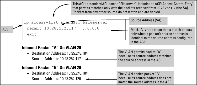
Suppose, for example, that you have configured the ACL in An ACL with an ACE that allows only one source address to filter inbound packets on VLAN 20. Because the mask is all zeros, the ACE policy dictates that a match occurs only when the source address on such packets is identical to the address configured in the ACE.
Examples allowing multiple IPv4 addresses
The following table provides examples of how to apply masks to meet various filtering requirements.
Using an IP Address and Inverse Mask in an Access Control Entry
| Address in the ACE | Mask | Policy for a match between a packet and the ACE | Allowed addresses |
|---|---|---|---|
| A: 10.38.252.195 | 0.0.0.255 | Exact match in first three octets only. |
10.38.252.<0-255> (See row A in Mask effect on selected octets of the IPv4 addresses in Table 30) |
| B: 10.38.252.195 | 0.0.7.255 | Exact match in the first two octets and the leftmost five bits (248) of the third octet. |
10.38.<248-255> .<0-255> (In the third octet, only the rightmost three bits are wildcard bits. The leftmost five bits must be a match, and in the ACE, these bits are all set to 1. See row B in Mask effect on selected octets of the IPv4 addresses in Table 30. |
| C: 10.38.252.195 | 0.0.0.0 | Exact match in all octets. |
10.38.252.195 (There are no wildcard bits in any of the octets. See row C in Mask effect on selected octets of the IPv4 addresses in Table 30.) |
| D: 10.38.252.195 | 0.15.255.255 | Exact match in the first octet and the leftmost four bits of the second octet. |
10.<32-47> .<0-255> .<0-255> (In the second octet, the rightmost four bits are wildcard bits. See row D in Mask effect on selected octets of the IPv4 addresses in Table 30.) |
Mask effect on selected octets of the IPv4 addresses in Using an IP Address and Inverse Mask in an Access Control Entry
| Addr | Octet | Mask | Octet range | 128 | 64 | 32 | 16 | 8 | 4 | 2 | 1 |
|---|---|---|---|---|---|---|---|---|---|---|---|
| A | 3 | 0 all bits | 252 | 1 | 1 | 1 | 1 | 1 | 1 | 0 | 0 |
| B | 3 | 7 last 3 bits | 248-255 | 1 | 1 | 1 | 1 | 1 | 0 or 1 | 0 or 1 | 0 or 1 |
| C | 4 | 0 all bits | 195 | 1 | 1 | 0 | 0 | 0 | 0 | 1 | 1 |
| D | 2 | 15 last 4 bits | 32-47 | 0 | 0 | 1 | 0 | 0 or 1 | 0 or 1 | 0 or 1 | 0 or 1 |
| Shaded areas indicate bit settings that must be an exact match. | |||||||||||
If there is a match between the policy in the ACE and the IPv4 address in a packet, the packet is either permitted or denied according to how the ACE is configured. If there is no match, the next ACE in the ACL is applied to the packet. The same operation applies to a destination IPv4 address used in an extended ACE.
Where an ACE includes both source and destination addresses, there is one address/ACL-mask pair for the source address, and another address/ACL-mask pair for the destination address. See Configuring named, standard ACLs.
Use CIDR notation to enter ACL masks. The switch interprets the bits specified with CIDR notation as the address bits in an ACL and the corresponding address bits in a packet that must match. The switch then converts the mask to inverse notation for ACL use.
Examples of CIDR notation for masks
| Address used in an ACL with CIDR notation | Resulting ACL mask | Meaning |
|---|---|---|
| 10.38.240.125/15 | 0.1.255.255 | The leftmost 15 bits must match; the remaining bits are wildcards. |
| 10.38.240.125/20 | 0.0.15.255 | The leftmost 20 bits must match; the remaining bits are wildcards. |
| 10.38.240.125/21 | 0.0.7.255 | The leftmost 21 bits must match; the remaining bits are wildcards. |
| 10.38.240.125/24 | 0.0.0.255 | The leftmost 24 bits must match; the remaining bits are wildcards. |
| 18.38.240.125/32 | 0.0.0.0 | All bits must match. |
-
Configure one or more ACLs. This creates and stores the ACLs in the switch configuration.
-
Assign an ACL. This step uses one of the following applications to assign the ACL to an interface:
-
If the ACL is applied as an RACL, enable IPv4 routing. Except for instances where the switch is the traffic source or destination, assigned RACLs filter IPv4 traffic only when routing is enabled on the switch.
The permit or deny policy for IPv4 traffic you want to filter can be based on source address alone, or on source address plus other IPv4 factors.
-
Standard ACL: Uses only a packet's source IPv4 address as a criterion for permitting or denying the packet. For a standard ACL ID, use either a unique numeric string in the range of 1-99 or a unique name string of up to 64 alphanumeric characters.
-
Extended ACL: Offers the following criteria as options for permitting or denying a packet:
-
-
Any TCP traffic (only) for a specific TCP port or range of ports, including optional use of TCP control bits or control of connection (established) traffic based on whether the initial request should be allowed
-
Any UDP traffic (only) or UDP traffic for a specific UDP port
-
Any ICMP traffic (only) or ICMP traffic of a specific type and code
For an extended ACL ID, use either a unique number in the range of 100-199 or a unique name string of up to 64 alphanumeric characters.
Carefully plan ACL applications before configuring specific ACLs. For more on this topic, see Configuring named, standard ACLs.
After you enter an ACL command, you may want to inspect the resulting configuration. This is especially true where you are entering multiple ACEs into an ACL. Also, it is helpful to understand the configuration structure when using the following information.
The basic ACL structure includes four elements:
-
ACL identity and type: This identifies the ACL as
standardorextendedand shows the ACL name or number. -
One or more deny/permit list entries (ACEs): One entry per line.
Element Notes Type Standard or Extended Identifier -
Alphanumeric; Up to 64 Characters, Including Spaces
-
Numeric: 1 - 99 (Standard) or 100 - 199 (Extended)
Remark Allows up to 100 alphanumeric characters, including blank spaces. (If any spaces are used, the remark must be enclosed in a pair of single or double quotes.) A remark is associated with a particular ACE and has the same sequence number as the ACE. (One remark is allowed per ACE.) See Attaching a remark to an ACE. Maximum ACEs Per per Switch The upper limit on ACEs supported by the switch depends on the concurrent resource usage by configured ACL, QoS, IDM, Mirroring, virus-throttling, and other features. See IPv4 ACL configuration and operating rules. -
-
Implicit Deny:Where an ACL is in use, it denies any packets that do not have a match with the ACEs explicitly configured in the list. The Implicit Deny does not appear in ACL configuration listings, but always functions when the switch uses an ACL to filter packets. (You cannot delete the Implicit Deny, but you cansupersede it with a
permit anyorpermit ip any anystatement.)
Individual ACEs in a standard ACL include only a permit/deny statement, the source addressing, and an optional log command (available with "deny" statements).

For example, the following figure shows how to interpret the entries in a standard ACL.

Individual ACEs in an extended ACL include:
-
A permit/deny statement
-
Source and destination IPv4 addressing
-
Choice of IPv4 criteria, including optional precedence and ToS
-
Optional ACL
logcommand (fordenyentries) -
Optional remark statements
For example, the following figure shows how to interpret the entries in an extended ACL.

When the switch uses an ACL to determine whether to permit or deny a packet, it compares the packet to the criteria specified in the individual ACEs in the ACL, beginning with the first ACE in the list and proceeding sequentially until a match is found. When a match is found, the switch applies the indicated action (permit or deny) to the packet. This is significant because, once a match is found for a packet, subsequent ACEs in the same ACL are not applied to that packet, regardless of whether they match the packet.
For example, suppose that you have applied the ACL shown in to inbound IPv4 traffic on VLAN 1 (the default VLAN):
Effect of the above ACL on inbound IPv4 traffic in the assigned VLAN
In any ACL having one or more ACEs, there is always a packet match. This is because the switch automatically applies an Implicit Deny as the last ACE in any ACL. This function is not visible in ACL listings, but is always present, see A standard ACL that permits all IPv4 traffic not implicitly denied. This means that if you configure the switch to use an ACL for filtering either inbound or outbound IPv4 traffic on a VLAN, any packets not specifically permitted or denied by the explicit entries you create are denied by the Implicit Deny action. If you want to preempt the Implicit Deny (so that IPv4 traffic not specifically addressed by earlier ACEs in a given ACL are permitted), insert an explicit permit any (for standard ACLs) or permit ip any any (for extended ACLs) as the last explicit ACE in the ACL.
The switch stores ACLs in the configuration file. Thus, until you actually assign an ACL to an interface, it is present in the configuration, but not used (and does not use any of the monitored resources, see "Monitored Resources" in the management and configuration guide for your switch.)
In this case, if you subsequently create an ACL with that name or number, the switch automatically applies each ACE as soon as you enter it in the running-config file. Similarly, if you modify an existing ACE in an ACL you already applied to an interface, the switch automatically implements the new ACE as soon as you enter it. The switch allows up to 2048 ACLs each for IPv4 and determines the total from the number of unique ACL names in the configuration.For example, if you configure two ACLs, but assign only one of them to a VLAN, the ACL total is two, for the two unique ACL names. If you then assign the name of a nonexistent ACL to a VLAN, the new ACL total is three, because the switch now has three unique ACL names in its configuration. (RADIUS-based ACL resources are drawn from the IPv4 allocation).
(For a summary of ACL resource limits, see the appendix covering scalability in the latest management and configuration guide for your switch.)
ACL logging enables the switch to generate a message when IP traffic meets the criteria for a match with an ACE that results in an explicit "deny" action. You can use ACL logging to help:
-
Test your network to ensure that your ACL configuration is detecting and denying the IPv4 traffic you do not want forwarded
-
Receive notification when the switch detects attempts to forward IPv4 traffic you have designed your ACLs to reject (deny)
The switch sends ACL messages to Syslog and optionally to the current console, Telnet, or SSH session. You can use logging <> to configure up to six Syslog server destinations.
-
The switch configuration must include an ACL assigned to a port, trunk, or static VLAN interface. This ACL must contain an ACE configured with the deny action and the log option.
-
If the RACL application is used, then IPv4 routing must be enabled on the switch.
-
For ACL logging to a Syslog server:
-
The server must be accessible to the switch and identified in the running configuration.
-
The logging facility must be enabled for Syslog.
-
Debug must be configured to:
-
support ACL messages
-
send debug messages to the desired debug destination
-
-
These requirements are described in more detail under Enabling ACL logging on the switch.
When the switch detects a packet match with an ACE and the ACE includes both the deny action and the optional log parameter, anACL log message is sent to the designated debug destination. The first time a packet matches an ACE with deny and log configured, the message is sent immediately to the destination and the switch starts a wait-period of approximately five minutes - the exact duration of the period depends on how the packets are internally routed. At the end of the collection period, the switch sends a single-line summary of any additional "deny" matches for that ACE, and any other "deny" ACEs for which the switch detected a match. If no further log messages are generated in the wait-period, the switch suspends the timer and resets itself to send a message as soon as a new "deny" match occurs. The data in the message includes the information illustrated in the following figure.
Syntax
Displays the current match (hit) count per ACE for the specified IPv4 or IPv6 static ACL assignment on a specific interface.
switch# show statistics aclv6 IPV6-ACL vlan 20 vlan
HitCounts for ACL IPV6-ACL
 Total Delta
 ( 12) ( 2) 10 permit icmp ::/0 fe80::20:2/128 128
 ( 6) ( 0) 20 deny tcp ::/0 fe80::20:2/128 eq 23 log
 ( 41) ( 10) 30 permit ipv6 ::/0 ::/0

The command displays a counter for each ACE in an ACL assigned to an interface on the switch:
This column lists the running total of the matches the switch has detected for the ACEs in an applied ACL since the ACL's counters were last reset, and includes the match count listed in the
Deltacolumn for the same ACE.For a given ACE in an assigned ACL, both counters increment by 1 each time the switch detects a packet that matches the criteria in that ACE. However, the
Totalcounter maintains the running total of the matches since the last reset, while theDeltacounter shows only the number of matches since either the last
show statistics[aclv4] | [aclv6>]command or the last time all counters in the ACL were reset.For example, in line 10 below, there has been a total of 37 matches on the ACE in line 10 since the last time the ACL's counters were reset, and 9 of those matches have occurred after the last
show statistics aclv4command.Total Delta ( 37) ( 9) 10 permit ip 0.0.0.0 255.255.255...
NOTE: This ACL monitoring feature does not include hits on the "implicit deny" that is included at the end of all ACLs.
Resetting ACE Hit Counters to Zero:
Removing an ACL from an interface zeros the ACL's ACE counters for that interface only.
For a given ACL, either of the following actions clear the ACE counters to zero for all interfaces to which the ACL is assigned.
adding or removing a permit or deny ACE in the ACL
rebooting the switch
Example of ACL Performance Monitoring
The following figure shows a sample of performance monitoring output for an IPv6 ACL assigned as a VACL.

The following figure shows a sample of performance monitoring output for an IPv4 ACL assigned as a VACL.
|
|
|
|
|
NOTE: The examples of counters in this section use small values to help illustrate counter operation. The counters in real-time network applications are generally much more active and show higher values. |
|
|
Where the same IPv6 ACL is assigned to multiple interfaces, the switch maintains a separate instance of each ACE counter in the ACL. When there is a match with traffic on one of the ACL's assigned interfaces, only the affected ACE counters for that interface are incremented. Other instances of the same ACL applied to other interfaces are not affected.
-
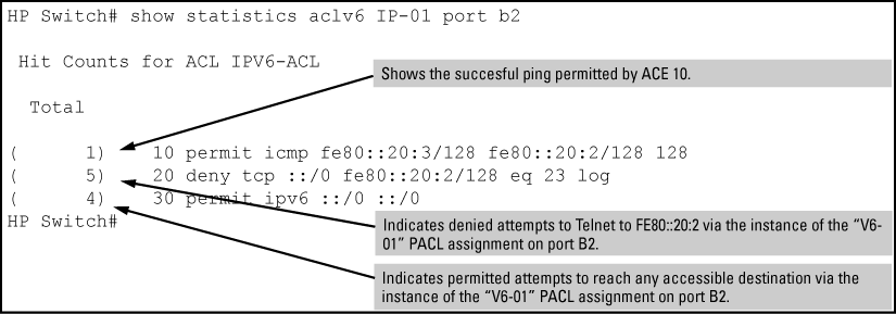
An ACL named "V6-01" is configured as shown in ACL "V6-01" and command for PACL assignment on port B2 to block Telnet access to a workstation at FE80::20:2 on VLAN 20.
-
The ACL is assigned as a PACL on port B2:

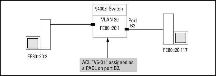
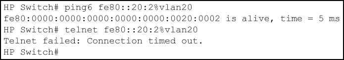
Using the topology in Application to filter traffic inbound on port B2, a workstation at FE80::20:117 on port B2 attempting to ping and Telnet to the workstation at FE80::20:2 is filtered through the PACL instance of the "V6-01" ACL assigned to port B2, resulting in the following:
Where the same IPv4 ACL is assigned to multiple interfaces as a VLAN ACL (VACL) or port ACL (PACL), the switch maintains a separate instance of ACE counters for each interface assignment. Thus, when there is a match with traffic on one of the ACL's VACL- or PACL -assigned interfaces, only the ACE counter in the affected instance of the ACL is incremented. However, if an ACL has multiple assignments as an RACL, then a match with an ACE in any RACL instance of the ACL increments that same counter on all RACL-assigned instances of that ACL. (The ACE counters for VACL and PACL instances of an ACL are not affected by counter activity in RACL instances of the same ACL.)
For example, suppose that an ACL named "Test-1" is configured as shown in ACL "Test-1" and interface assignment commands to block Telnet access to a server at 10.10.20.12 on VLAN 20, and that the Test-1 ACL is assigned to VLANs as follows:
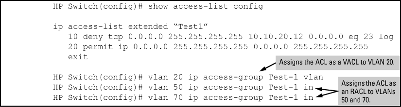

-
Matches with ACEs 10 or 20 that originate on VLAN 20 increment only the counters for the instances of these two ACEs in the Test-1 VACL assignment on VLAN 20. The same counters in the instances of ACL Test-1 assigned to VLANs 50 and 70 are not be incremented.
-
Any Telnet requests to 10.10.20.12 that originate on VLANs 50 or 70 are filtered by instances of Test-1 assigned as RACLs, and increment the counters for ACE 10 on both RACL instances of the Test-1 ACL.
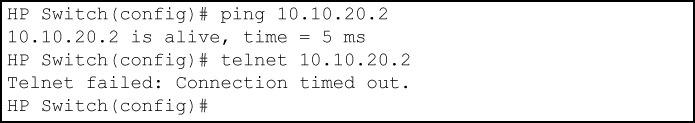
Using the network in Access Granted page, a device at 10.10.20.4 on VLAN 20 attempting to ping and Telnet to 10.10.20.2 is filtered through the VACL instance of the "Test-1" ACL on VLAN 20 and results in the following:
Ping and telnet from 10.10.20.4 to 10.10.20.2 filtered by the assignment of "Test-1" as a VACL on VLAN 20
For more information, see "GVRP" in the advanced traffic management guide.
3. If you disable the use of dynamic VLANs in an authentication session using the no aaa port-access gvrp-vlans command, client sessions that were authenticated with a dynamic VLAN continue and are not deauthenticated.
Note: This behavior differs from how static VLAN assignment is handled in an authentication session. If you remove the configuration of the static VLAN used to create a temporary client session, the 802.1X, MAC, or Web authenticated client is deauthenticated.
However, if a RADIUS-configured dynamic VLAN used for an authentication session is deleted from the switch through normal GVRP operation (for example, if no GVRP advertisements for the VLAN are received on any switch port), authenticated clients using this VLAN are deauthenticated.
802.1X on the the switches includes the following:
-
Switch operation as both an authenticator (for supplicants having a point-to-point connection to the switch) and as a supplicant for point-to-point connections to other 802.1X-aware switches.
-
Authentication of 802.1X access using a RADIUS server and either the EAP or CHAP protocol.
-
Provision for enabling clients that do not have 802.1 supplicant software to use the switch as a path for downloading the software and initiating the authentication process (802.1X Open VLAN mode).
-
User-Based access control option with support for up to 32 authenticated clients per-port.
-
Port-Based access control option allowing authentication by a single client to open the port. This option does not force a client limit and, on a port opened by an authenticated client, allows unlimited client access without requiring further authentication.
-
Supplicant implementation using CHAP authentication and independent user credentials on each port.
-
-
The local operator password configured with the
passwordcommand for management access to the switch is no longer accepted as an 802.1X authenticator credential. Thepassword port-accesscommand configures the local operator user name and password used as 802.1X authentication credentials for access to the switch. The values configured can be stored in a configuration file using theinclude-credentialscommand. -
On-demand change of a port's configured VLAN membership status to support the current client session.
-
Session accounting with a RADIUS server, including the accounting update interval.
-
Use of Show commands to display session counters.
-
Support for concurrent use of 802.1X and either Web authentication or MAC authentication on the same port.
-
For unauthenticated clients that do not have the necessary 802.1X supplicant software (or for other reasons related to unauthenticated clients), there is the option to configure an Unauthorized-Client VLAN. This mode allows you to assign unauthenticated clients to an isolated VLAN through which you can provide the necessary supplicant software and other services you want to extend to these clients.
The switch offers two methods for using 802.1X access control. Generally, the "Port Based" method supports one 802.1X-authenticated client on a port, which opens the port to an unlimited number of clients. The "User-Based" method supports up to 32 802.1X-authenticated clients on a port. In both cases, there are operating details to be aware of that can influence your choice of methods.
802.1X operation with access control on aper-user basis provides client-level security that allows LAN access to individual 802.1X clients (up to 32 per port), where each client gains access to the LAN by entering valid user credentials. This operation improves security by opening a given port only to individually authenticated clients, while simultaneously blocking access to the same port for clients that cannot be authenticated. All sessions must use the same untagged VLAN. Also, an authenticated client can use any tagged VLAN memberships statically configured on the port, provided the client is configured to use the tagged VLAN memberships available on the port. Note: The session total includes any sessions begun by the Web Authentication or MAC Authentication features covered in Option for authenticator ports: configure port-security to allow only 802.1X-authenticated devices.
802.1X port-based access control provides port-level security that allows LAN access only on ports where a single 802.1X-capable client (supplicant) has entered authorized RADIUS user credentials. For reasons outlined below, this option is recommended for applications where only one client at a time can connect to the port. Using this option, the port processes all IP traffic as if it comes from the same client. Thus, in a topology where multiple clients can connect to the same port at the same time:
-
If the first client authenticates and opens the port, and then another client authenticates, the port responds as if the original client has initiated a reauthentication. With multiple clients authenticating on the port, the RADIUS configuration response to the latest client authentication replaces any other configuration from an earlier client authentication. If all clients use the same configuration this should not be a problem. But if the RADIUS server responds with different configurations for different clients, then the last client authenticated effectively locks out any previously authenticated client. When any client to authenticate closes its session, the port also closes and remains so until another client successfully authenticates.
-
The most recent client authentication determines the untagged VLAN membership for the port. Also, any client able to use the port can access any tagged VLAN memberships statically configured on the port, provided the client is configured to use the available, tagged VLAN memberships.
-
If the first client authenticates and opens the port, and then one or more other clients connect without trying to authenticate, then the port configuration as determined by the original RADIUS response remains unchanged and all such clients have the same access as the authenticated client. When the authenticated client closes the session, the port is also closed to any other unauthenticated clients using the port.
This operation unblocks the port while an authenticated client session is in progress. In topologies where simultaneous, multiple client access is possible this can allow unauthorized and unauthenticated access by another client while an authenticated client is using the port. If you want to allow only authenticated clients on the port, then user-based access control should be used instead of port-based access control. Using the user-based method enables you to specify up to 32 authenticated clients. See 802.1X User-based access control.
|
|
|
|
|
NOTE: Port-Based 802.1X can operate concurrently with Web-Authentication or MAC-Authentication on the same port. However, this is not a commonly used application and is not generally recommended. For more information, see Operating notes and guidelines. |
|
|
Note that you can also configure 802.1X for authentication through the switch local user name and password instead of a RADIUS server, but doing so increases the administrative burden, decentralizes user credential administration, and reduces security by limiting authentication to one Operator password set for all users.
The switches covered in this guide also provide RADIUS Network accounting for 802.1X access. See RADIUS Authentication, Authorization, and Accounting.
This operation provides security on a point-to-point link between a client and the switch, where both devices are 802.1X-aware. If you expect desirable clients that do not have the necessary 802.1X supplicant software, you can provide a path for downloading such software by using the 802.1X Open VLAN mode, see 802.1X Open VLAN mode.
Example of the authentication process
Suppose you have configured a port on the switch for 802.1X authentication operation, which blocks access to the LAN through that port. If you then connect an 802.1X-aware client (supplicant) to the port and attempt to log on:
The client responds with a user name that uniquely defines this request for the client.
The switch responds in one of the following ways:
If 802.1X on the switch is configured for RADIUS authentication, the switch then forwards the request to a RADIUS server.
The server responds with an access challenge which the switch forwards to the client.
The client then provides identifying credentials (such as a user certificate), which the switch forwards to the RADIUS server.
The RADIUS server then checks the credentials provided by the client.
If the client is successfully authenticated and authorized to connect to the network, then the server notifies the switch to allow access to the client. Otherwise, access is denied and the port remains blocked.
If 802.1X on the switch is configured for local authentication, then:
The switch compares the client's credentials to the user name and password configured in the switch (Operator level).
If the client is successfully authenticated and authorized to connect to the network, then the switch allows access to the client. Otherwise, access is denied and the port remains blocked for that client.
NOTE: Switches use either 802.1X port-based authentication or 802.1X user-based authentication. For more information, see User authentication methods.
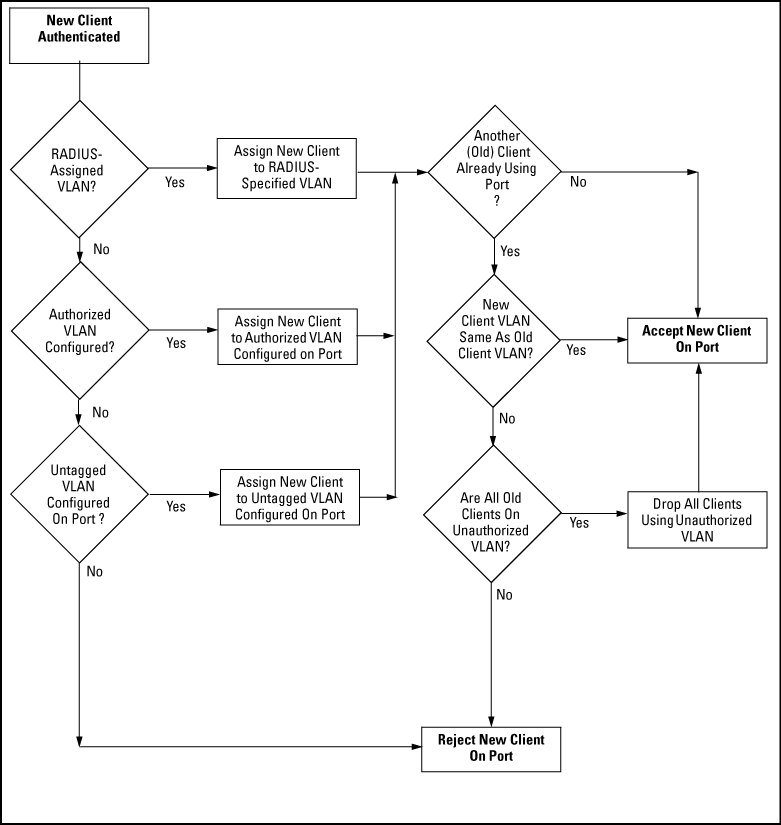
Following client authentication, an 802.1X port resumes membership in any tagged VLANs for which it is already assigned in the switch configuration. The port also becomes an untagged member of one VLAN according to the following order of options:
-
1st Priority: The port joins a VLAN to which it has been assigned by a RADIUS server during client authentication.
-
2nd Priority: If RADIUS authentication does not include assigning the port to a VLAN, then the switch assigns the port to the VLAN entered in the port's 802.1X configuration as an Authorized-Client VLAN, if configured.
-
3rd Priority: If the port does not have an Authorized-Client VLAN configured, but does have a static, untagged VLAN membership in its configuration, then the switch assigns the port to this VLAN.
A port assigned to a VLAN by an Authorized-Client VLAN configuration (or a RADIUS server) is an untagged member of the VLAN for the duration of the authenticated session. This applies even if the port is also configured in the switch as a tagged member of the same VLAN.
|
|
|
|
|
NOTE: On switches, using the same port for both RADIUS-assigned clients and clients using a configured, Authorized-Client VLAN is not recommended. Doing so can result in authenticated clients with mutually exclusive VLAN priorities, meaning some authenticated clients can be denied access to the port. See Priority of VLAN assignment for an authenticated client. |
|
|
-
In the user-based mode, when there is an authenticated client on a port, the following traffic movement is allowed:
-
Multicast and broadcast traffic
-
Unicast traffic to authenticated clients
-
All traffic from authenticated clients.
-
-
When a port on the switch is configured as either an authenticator or supplicant and is connected to another device, rebooting the switch causes a re-authentication of the link.
-
Using user-based 802.1X authentication, when a port on the switch is configured as an authenticator the port allows only authenticated clients up to the currently configured client limit.
For clients without proper 802.1X supplicant software, the optional 802.1X Open VLAN mode can be used to open a path for downloading 802.1X supplicant software to a client or to provide other services for unauthenticated clients. See 802.1X Open VLAN mode.
-
Using port-based 802.1X authentication when a port on the switch is configured as an authenticator, one authenticated client opens the port. Other clients not running an 802.1X supplicant application can have access to the switch and network through the opened port. If another client uses an 802.1X supplicant application to access the opened port, re-authentication occurs using the RADIUS configuration response for the latest client to authenticate. To control access by all clients, use the user-based method.
-
Where a switch port is configured with user-based authentication to accept multiple 802.1X (and Web- or MAC-Authentication) client sessions, all authenticated clients must use the same port-based, untagged VLAN membership assigned for the earliest, currently active client session. Thus, on a port where one or more authenticated client sessions are already running, all such clients are on the same untagged VLAN. If a RADIUS server subsequently authenticates a new client, but attempts to re-assign the port to a different, untagged VLAN than the one already in use for the previously existing, authenticated client sessions, the connection for the new client fails. For more on this topic, see 802.1X Open VLAN mode.
NOTE: If the port is statically configured with any tagged VLAN memberships, any authenticated client configured to use these tagged VLANs has access to them.
-
If a port on switch "A" is configured as an 802.1X supplicant and is connected to a port on another switch, "B", that is not 802.1X-aware, access to switch "B" occurs without 802.1X security protection.
-
On a port configured for 802.1X with RADIUS authentication, if the RADIUS server specifies a VLAN for the supplicant and the port is a trunk member, the port is blocked. If the port is later removed from the trunk, the port allows authentication of the supplicant. Similarly, if the supplicant is authenticated and later the port becomes a trunk member, the port is blocked. If the port is then removed from the trunk, it allows the supplicant to re-authenticate.
-
If a client already has access to a switch port when you configure the port for 802.1X authenticator operation, the port blocks the client from further network access until it can be authenticated.
-
Meshing is not supported on ports configured for 802.1X port-access security.
-
A port can be configured as an authenticator or an 802.1X supplicant, or both. Some configuration instances block traffic flow or allow traffic to flow without authentication. See Configuring switch ports as 802.1X authenticators and Configuring Switch Ports To Operate As Supplicants for 802.1X Connections to Other Switches.
-
To help maintain security, 802.1X and LACP cannot both be enabled on the same port. If you try to configure 802.1X on a port already configured for LACP (or the reverse) you see a message similar to the following:
While 802.1X port-based access control can operate concurrently with Web Authentication or MAC Authentication, port-based access control is subordinate to Web-Auth and MAC-Auth operation. If 802.1X operates in port-based mode and MAC or Web authentication is enabled on the same port, any 802.1X authentication has no effect on the ability of a client to access the controlled port. That is, the client's access is denied until the client authenticates through Web-Auth or MAC-Auth on the port. Note: A client authenticating with port-based 802.1X does not open the port in the same way that it would if Web-Auth or MAC-Auth were not enabled. Any non-authenticating client attempting to access the port after another client authenticates with port-based 802.1X still has to authenticate through Web-Auth or MAC-Auth.
When a PC is connected through an IP phone to a switch port that has been authorized using 802.1X or Web/MAC authentication, the IP phone is authenticated using client-based 802.1X or Web/MAC authentication and has access to secure, tagged VLANs on the port. If the PC is unauthenticated, it needs to have access to the insecure guest VLAN (unauthenticated VLAN) that has been configured for 802.1X or Web/MAC authentication. 802.1X and Web/MAC authentication normally do not allow authenticated clients (the phone) and unauthenticated clients (the PC) on the same port.
Mixed port access mode allows 802.1X and Web/MAC authenticated and unauthenticated clients on the same port when the guest VLAN is the same as the port's current untagged authenticated VLAN for authenticated clients, or when none of the authenticated clients are authorized on the untagged authenticated VLAN. Instead of having just one client per port, multiple clients can use the guest VLAN.
Authenticated clients always have precedence over unauthenticated clients if access to a client's untagged VLAN requires removal of a guest VLAN from the port. If an authenticated client becomes authorized on its untagged VLAN as the result of initial authentication or because of an untagged packet from the client, then all 802.1X or Web/MAC authenticated guests are removed from the port and the port becomes an untagged member of the client's untagged VLAN.
-
The port sends broadcast traffic from the VLANs even when there are only guests authorized on the port.
-
Guests can use the same bandwidth, rate limits and QoS settings that may be assigned for authenticated clients on the port (via RADIUS attributes).
-
When no authenticated clients are authorized on the untagged authenticated VLAN, the port becomes an untagged member of the guest VLAN for as long as no untagged packets are received from any authenticated clients on the port.
-
New guest authorizations are not allowed on the port if at least one authenticated client is authorized on its untagged VLAN and the guest VLAN is not the same as the authenticated client's untagged VLAN.
|
|
|
|
|
NOTE: If you disable mixed port access mode, this does not automatically remove guests that have already been authorized on a port where an authenticated client exists. New guests are not allowed after the change, but the existing authorized guests are still authorized on the port until they are removed by a new authentication, an untagged authorization, a port state change, and so on. |
|
|
This section describes using the 802.1X Open VLAN mode to provide a path for clients that need to acquire 802.1X supplicant software before proceeding with the authentication process. The Open VLAN mode involves options for configuring unauthorized-client and authorized-client VLANs on ports configured as 802.1X authenticators.
Configuring the 802.1X Open VLAN mode on a port changes how the port responds when it detects a new client. In earlier releases, a "friendly" client computer not running 802.1X supplicant software could not be authenticated on a port protected by 802.1X access security. As a result, the port would become blocked and the client could not access the network. This prevented the client from:
-
Acquiring IP addressing from a DHCP server
-
Downloading the 802.1X supplicant software necessary for an authentication session
The 802.1X Open VLAN mode solves this problem by temporarily suspending the port's static VLAN memberships and placing the port in a designated Unauthorized-Client VLAN (sometimes termed a guest VLAN). In this state the client can proceed with initialization services, such as acquiring IP addressing and 802.1X client software, and starting the authentication process.
Following client authentication, an 802.1X port resumes membership in any tagged VLANs for which it is already assigned in the switch configuration. The port also becomes an untagged member of one VLAN according to the following order of options:
-
1st Priority: The port joins a VLAN to which it has been assigned by a RADIUS server during client authentication.
-
2nd Priority: If RADIUS authentication does not include assigning the port to a VLAN, then the switch assigns the port to the VLAN entered in the port's 802.1X configuration as an Authorized-Client VLAN, if configured.
-
3rd Priority: If the port does not have an Authorized-Client VLAN configured, but does have a static, untagged VLAN membership in its configuration, then the switch assigns the port to this VLAN.
A port assigned to a VLAN by an Authorized-Client VLAN configuration (or a RADIUS server) is an untagged member of the VLAN for the duration of the authenticated session. This applies even if the port is also configured in the switch as a tagged member of the same VLAN.
You can apply the 802.1X Open VLAN mode in more than one way. Depending on your use, you might need to create one or two static VLANs on the switch for exclusive use by per-port 802.1X Open VLAN mode authentication:
-
Unauthorized-Client VLANConfigure this VLAN when unauthenticated, friendly clients need access to some services before being authenticated or instead of being authenticated.
-
Authorized-Client VLANConfigure this VLAN for authenticated clients when the port is not statically configured as an untagged member of a VLAN you want clients to use, or when the port is statically configured as an untagged member of a VLAN you do not want clients to use. Note: A port can be configured as untagged on only one port-based VLAN. When an Authorized-Client VLAN is configured, it is always untagged and blocks the port from using a statically configured, untagged membership in another VLAN. After client authentication, the port returns to membership in any tagged VLANs for which it is configured.
802.1X Open VLAN mode options
| Condition | Rule | ||||||
|---|---|---|---|---|---|---|---|
| Static VLANs used as Authorized-Client or Unauthorized-Client VLANs | These must be configured on the switch before you configure an 802.1X authenticator port to use them. Use the vlan <vlan-id> command or the VLAN Menu screen in the Menu interface. |
||||||
| VLAN assignment received from a RADIUS server | If the RADIUS server specifies a VLAN for an authenticated supplicant connected to an 802.1X authenticator port, this VLAN assignment overrides any Authorized-Client VLAN assignment configured on the authenticator port. This is because membership in both VLANs is untagged, and the switch allows only one untagged, port-based VLAN membership per-port.
For example, suppose you configured port A4 to place authenticated supplicants in VLAN 20. If a RADIUS server authenticates supplicant "A" and assigns this supplicant to VLAN 50, then the port can access VLAN 50 as an untagged member while the client session is running. When the client disconnects from the port the port drops these assignments and uses the untagged VLAN memberships for which it is statically configured. After client authentication, the port resumes any tagged VLAN memberships for which it is already configured. |
||||||
| Temporary VLAN membership during a client session |
|
||||||
| Effect of Unauthorized-Client VLAN session on untagged port VLAN membership |
|
||||||
| Effect of Authorized-Client VLAN session on untagged port VLAN membership. |
|
||||||
| Multiple Authenticator ports using the same Unauthorized-Client and Authorized-Client VLANs |
You can use the same static VLAN as the Unauthorized-Client VLAN for all 802.1X authenticator ports configured on the switch. Similarly, you can use the same static VLAN as the Authorized-Client VLAN for all 802.1X authenticator ports configured on the switch.
|
||||||
|
Effect of failed Client Authentication attempt This rule assumes no other authenticated clients are already using the port on a different VLAN. |
When there is an Unauthorized-Client VLAN configured on an 802.1X authenticator port, an unauthorized client connected to the port has access only to the network resources belonging to the Unauthorized-Client VLAN. This access continues until the client disconnects from the port. (If there is no Unauthorized-Client VLAN configured on the authenticator port, the port simply blocks access for any unauthorized client.) | ||||||
|
Effect of RADIUS-assigned VLAN This rule assumes no other authenticated clients are already using the port on a different VLAN. |
The port joins the RADIUS-assigned VLAN as an untagged member. | ||||||
| IP addressing for a client connected to a port configured for 802.x Open VLAN mode | A client can either acquire an IP address from a DHCP server or use a manually configured IP address before connecting to the switch. | ||||||
| 802.1X supplicant software for a client connected to a port configured for 802.1X Open VLAN mode | A friendly client, without 802.1X supplicant software, connecting to an authenticator port must be able to download this software from the Unauthorized-Client VLAN before authentication can begin. | ||||||
| Switch with a port configured to allow multiple Authorized-Client sessions | When a new client is authenticated on a given port:
|
||||||
|
Note: Limitation on using an Unauthorized-Client VLAN on an 802.1X port configured to allow multiple-client access |
You can optionally enable switches to allow up to 32 clients per-port. The Unauthorized-Client VLAN feature can operate on an 802.1X-configured port regardless of how many clients the port is configured to support. However, all clients on the same port must operate through the same untagged VLAN membership. This means that any client accessing a given port must be able to authenticate and operate on the same VLAN as any other previously authenticated clients that are currently using the port.
Thus, an Unauthorized-Client VLAN configured on a switch port that allows multiple 802.1X clients cannot be used if there is already an authenticated client using the port on another VLAN. Also, a client using the Unauthenticated-Client VLAN is blocked when another client becomes authenticated on the port. For this reason, the best utilization of the Unauthorized-Client VLAN feature is in instances where only one client is allowed per-port. Otherwise, unauthenticated clients are subject to being blocked at any time by authenticated clients using a different VLAN. Note: Using the same VLAN for authenticated and unauthenticated clients can create a security risk and is not recommended. |
Examine the switch current VLAN status by using the show port-access authenticator vlan andshow port-access authenticator <port-list>
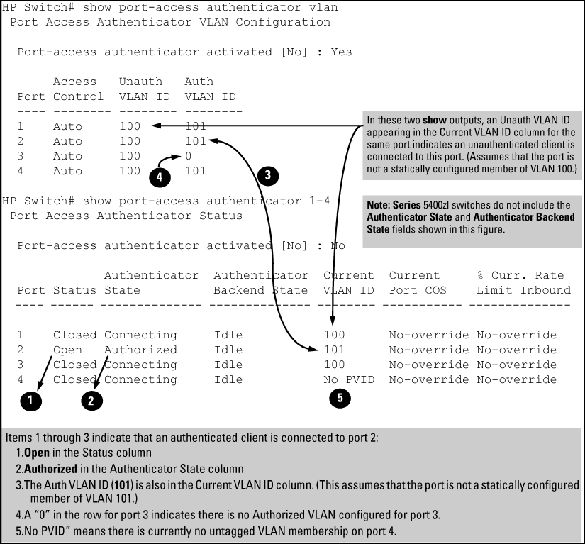
In the output shown in Showing ports configured for open VLAN mode:
-
When the Auth VLAN ID is configured and matches the
Current VLAN ID, an authenticated client is connected to the port. This assumes the port is not a statically configured member of the VLAN you are using for Auth VLAN. -
When the
Unauth VLAN IDis configured and matches theCurrent VLAN ID, an unauthenticated client is connected to the port. This assumes the port is not a statically configured member of the VLAN you are using for Unauth VLAN.
|
|
|
|
|
NOTE: Because a temporary Open VLAN port assignment to either an authorized or unauthorized VLAN is an untagged VLAN membership, these assignments temporarily replace any other untagged VLAN membership that is statically configured on the port. For example, if port 12 is statically configured as an untagged member of VLAN 1, but is configured to use VLAN 25 as an authorized VLAN, then the port's membership in VLAN 1 is temporarily suspended whenever an authenticated 802.1X client is attached to the port. |
|
|
Output for determining Open VLAN mode status Showing ports configured for open VLAN mode.
Output for determining Open VLAN mode status Showing ports configured for open VLAN mode.
| Status indicator | Meaning |
|---|---|
Status |
Either no client is connected or the connected client has not received authorization through 802.1X authentication.
An authorized 802.1X supplicant is connected to the port. |
Current VLAN ID |
Lists the VID of the static, untagged VLAN to which the port currently belongs.
|
Current Port CoS |
|
% Curr. Rate Limit Inbound |
-
Although you can configure Open VLAN mode to use the same VLAN for both the Unauthorized-Client VLAN and the Authorized-Client VLAN, this is not recommended. Doing so allows unauthenticated clients access to a VLAN intended only for authenticated clients, which poses a security breach.
-
While an Unauthorized-Client VLAN is in use on a port, the switch temporarily removes the port from any other statically configured VLAN for which that port is configured as a member. Note that the Menu interface still displays the port's statically configured VLANs.
-
A VLAN used as the Unauthorized-Client VLAN should not allow access to resources that must be protected from unauthenticated clients.
-
If a port is configured as a tagged member of VLAN "X", then the port returns to tagged membership in VLAN "X" upon successful client authentication. This happens even if the RADIUS server assigns the port to another, authorized VLAN "Y". Note: If RADIUS assigns VLAN "X" as an authorized VLAN, then the port becomes an untagged member of VLAN "X" for the duration of the client connection. If there is no Authorized-Client or RADIUS-assigned VLAN, then an authenticated client without tagged VLAN capability can access only a statically configured, untagged VLAN on that port.
-
When a client's authentication attempt on an Unauthorized-Client VLAN fails, the port remains a member of the Unauthorized-Client VLAN until the client disconnects from the port.
-
During an authentication session on a port in 802.1X Open VLAN mode, if RADIUS specifies membership in an untagged VLAN, this assignment overrides port membership in the Authorized-Client VLAN. If there is no Authorized-Client VLAN configured the RADIUS assignment overrides any untagged VLAN for which the port is statically configured.
-
If the only authenticated client on a port loses authentication during a session in 802.1X Open VLAN mode, the port VLAN membership reverts back to the Unauthorized-Client VLAN. If there is no Unauthorized-Client VLAN configured, then the client loses access to the port until it can reauthenticate itself. If there are multiple clients authenticated on the port, if one client loses access and attempts to re-authenticate, that client is handled as a new client on the port.
-
The first client to authenticate on a port configured to support multiple clients determines the port's VLAN membership for any subsequent clients that authenticate while an active session is already in effect.
|
|
|
|
|
NOTE: If 802.1X port-access is configured on a given port, then port-security |
|
|
In addition to the above, to use port-security on an authenticator port use the per-port client-limit option to control how many MAC addresses of 802.1X-authenticated devices the port is allowed to learn.
|
|
|
|
|
NOTE: Using |
|
|
If 802.1X authentication is disabled on a port or set to authorized (Force Authorize), the port can allow access to a non-authenticated client. Port-Security operates with 802.1X authentication only if the selected ports are configured as 802.1X with the control mode in the port-access authenticator command set to auto (the default setting). For example, if port A10 was at a non-default 802.1X setting and you wanted to configure it to support the port-security option, use the following aaa port-access command:
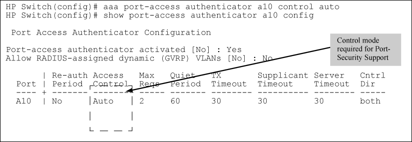
For each port configured as a supplicant, show port-access supplicant statistics <port-list> displays the source MAC address and statistics for transactions with the authenticator device most recently detected on the port. If the link between the supplicant port and the authenticator device fails, the supplicant port continues to show data received from the connection to the most recent authenticator device until one of the following occurs:
-
The supplicant port detects a different authenticator device.
-
You use the aaa port-access supplicant <port-list> clear-statistics command to clear the statistics for the supplicant port.
-
The switch reboots.
Thus, if the supplicant's link to the authenticator fails, the supplicant retains the transaction statistics it most recently received until one of the above events occurs. If moving a link with an authenticator from one supplicant port to another without clearing the statistics data from the first port, the authenticator's MAC address appears in the supplicant statistics for both ports.
RADIUS authentication for an 802.1X client on a given port can include a (static) VLAN requirement. For more details see the documentation provided with your RADIUS application. The static VLAN to which a RADIUS server assigns a client must already exist on the switch. If it does not exist or is a dynamic VLAN created by GVRP, authentication fails. Also, for the session to proceed, the port must be an untagged member of the required VLAN. If it is not, the switch temporarily reassigns the port as described below.
When a client is authenticated on port "N", if port "N" is not already configured as an untagged member of the static VLAN specified by the RADIUS server, then the switch temporarily assigns port "N" as an untagged member of the required VLAN for the duration of the 802.1X session. At the same time, if port "N" is already configured as an untagged member of another VLAN, port "N" loses access to that other VLAN for the duration of the session. This is because a port can be an untagged member of only one VLAN at a time.
Using a RADIUS server to authenticate clients, you can provide port-level security protection from unauthorized network access for the following authentication methods:
-
802.1X: Port-based or client-based access control to open a port for client access after authenticating valid user credentials.
-
MAC address: Authenticates a device's MAC address to grant access to the network.
-
WebAgent: Authenticates clients for network access using a webpage for user login.
|
|
|
|
|
NOTE: You can use 802.1X (port-based or client-based) authentication and either Web or MAC authentication at the same time on a port, with a maximum of 32 clients allowed on the port. The default is one client. Web authentication and MAC authentication are mutually exclusive on the same port. Also, you must disable LACP on ports configured for any of these authentication methods. For more information, see Web-based and MAC authentication. |
|
|
Following client authentication, VLAN configurations on a port are managed as follows when you use 802.1X, MAC, or Web authentication:
-
The port resumes membership in any tagged VLANs for which it is already assigned in the switch configuration. Tagged VLAN membership allows a port to be a member of multiple VLANs simultaneously.
-
The port is temporarily assigned as a member of an untagged (static or dynamic) VLAN for use during the client session according to the following order of options.
-
The port joins the VLAN to which it has been assigned by a RADIUS server during client authentication.
-
If RADIUS authentication does not include assigning the port to a VLAN, then the switch assigns the port to the authorized-client VLAN configured for the authentication method.
-
If the port does not have an authorized-client VLAN configured, but is configured for membership in an untagged VLAN, the switch assigns the port to this untagged VLAN.
-
-
During client authentication, a port assigned to a VLAN by a RADIUS server or an authorized-client VLAN configuration is an untagged member of the VLAN for the duration of the authenticated session. This applies even if the port is also configured in the switch as a tagged member of the same VLAN. The following restrictions apply:
-
If the port is assigned as a member of an untagged static VLAN, the VLAN must already be configured on the switch. If the static VLAN configuration does not exist, the authentication fails.
-
If the port is assigned as a member of an untagged dynamic VLAN that was learned through GVRP, the dynamic VLAN configuration must exist on the switch at the time of authentication and GVRP-learned dynamic VLANs for port-access authentication must be enabled.
If the dynamic VLAN does not exist or if you have not enabled the use of a dynamic VLAN for authentication sessions on the switch, the authentication fails.
-
-
To enable the use of a GVRP-learned (dynamic) VLAN as the untagged VLAN used in an authentication session, enter the
aaa port-access gvrp-vlanscommand, as described in . -
Enabling the use of dynamic VLANs in an authentication session offers the following benefits:
For information on how to enable the switch to dynamically create 802.1Q-compliant VLANs on links to other devices using the GARP VLAN Registration Protocol (GVRP), see "GVRP" in the advanced traffic management guide for your switch.
-
For an authentication session to proceed, a port must be an untagged member of the (static or dynamic) VLAN assigned by the RADIUS server (or an authorized-client VLAN configuration). The port temporarily drops any current untagged VLAN membership.
If the port is not already a member of the RADIUS-assigned (static or dynamic) untagged VLAN, the switch temporarily reassigns the port as an untagged member of the required VLAN for the duration of the session. At the same time, if the port is already configured as an untagged member of a different VLAN, the port loses access to the other VLAN for the duration of the session. A port can be an untagged member of only one VLAN at a time.
When the authentication session ends, the switch removes the temporary untagged VLAN assignment and re-activates the temporarily disabled, untagged VLAN assignment.
-
If GVRP is already enabled on the switch, the temporary untagged (static or dynamic) VLAN created on the port for the authentication session is advertised as an existing VLAN.
If this temporary VLAN assignment causes the switch to disable a different untagged static or dynamic VLAN configured on the port, as described in the preceding bullet and in Example of untagged VLAN assignment in a RADIUS-based authentication session, the disabled VLAN assignment is not advertised. When the authentication session ends, the switch:
-
Removes the temporary untagged VLAN assignment and stops advertising it.
-
Re-activates and resumes advertising the temporarily disabled, untagged VLAN assignment.
-
-
If you modify a VLAN ID configuration on a port during an 802.1X, MAC, or Web authentication session, the changes do not take effect until the session ends.
-
When a switch port is configured with RADIUS-based authentication to accept multiple 802.1X and MAC or Web authentication client sessions, all authenticated clients must use the same port-based, untagged VLAN membership assigned for the earliest, currently active client session.
Therefore, on a port where one or more authenticated client sessions are already running, all such clients are on the same untagged VLAN. If a RADIUS server subsequently authenticates a new client, but attempts to re-assign the port to a different, untagged VLAN than the one already in use for the previously existing, authenticated client sessions, the connection for the new client fails.
Example of untagged VLAN assignment in a RADIUS-based authentication session
The following example shows how an untagged static VLAN is temporarily assigned to a port for use during an 802.1X authentication session. In the example, an 802.1X-aware client on port A2 has been authenticated by a RADIUS server for access to VLAN 22. However, port A2 is not configured as a member of VLAN 22 but as a member of untagged VLAN 33 as shown in An active VLAN configuration.
Example
Suppose that a RADIUS-authenticated, 802.1X-aware client on port A2 requires access to VLAN 22, but VLAN 22 is configured for no access on port A2, and VLAN 33 is configured as untagged on port A2:
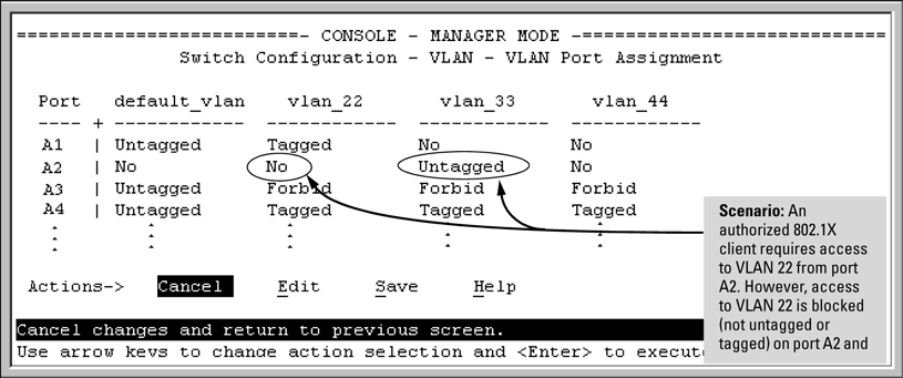
In An active VLAN configuration, if RADIUS authorizes an 802.1X client on port A2 with the requirement that the client use VLAN 22, then:
-
VLAN 22 becomes available as Untagged on port A2 for the duration of the session.
-
VLAN 33 becomes unavailable to port A2 for the duration of the session (because there can be only one untagged VLAN on any port).
To view the temporary VLAN assignment as a change in the active configuration, use the show vlan <vlan-id> command as shown in The active configuration for VLAN 22 temporarily changes for the 802.1X session where <vlan-id> is the (static or dynamic) VLAN used in the authenticated client session.

However, as shown in An active VLAN configuration, because VLAN 33 is configured as untagged on port A2 and because a port can be untagged on only one VLAN, port A2 loses access to VLAN 33 for the duration of the 802.1X session on VLAN 22.
You can verify the temporary loss of access to VLAN 33 by entering the show vlan 33 command as shown in The active configuration for VLAN 33 temporarily drops port 22 for the 802.1X session.

When the 802.1X client's session on port A2 ends, the port removes the temporary untagged VLAN membership. The static VLAN (VLAN 33) that is "permanently" configured as untagged on the port becomes available again. Therefore, when the RADIUS-authenticated 802.1X session on port A2 ends, VLAN 22 access on port A2 also ends, and the untagged VLAN 33 access on port A2 is restored as shown in The active configuration for VLAN 33 restores port A2 after the 802.1X session ends.

802.1X Operating Messages
| Message | Meaning |
|---|---|
|
|
The ports in the port list have not been enabled as 802.1X authenticators. Use this command to enable the ports as authenticators:
|
|
|
Occurs when there is an attempt to change the supplicant configuration on a port that is not currently enabled as a supplicant. Enable the port as a supplicant and then make the desired supplicant configuration changes. See Enabling a Switch Port as a Supplicant.. |
|
|
This message can appear if you configured the switch for EAP-RADIUS or CHAP-RADIUS authentication, but the switch does not receive a response from a RADIUS server. Ensure that the switch is configured to access at least one RADIUS server. Use show radius. If you also see the message Can't reach RADIUS server <x.x.x.x>, try the suggestions listed for that message. |
|
|
To maintain security, LACP is not allowed on ports configured for 802.1X authenticator operation. If you configure port security on a port on which LACP (active or passive) is configured, the switch removes the LACP configuration, displays a notice that LACP is disabled on the ports, and enables 802.1X on that port. Also, the switch does not allow you to configure LACP on a port on which port access (802.1X) is enabled. |