Multicast ARP configuration example
Network requirements
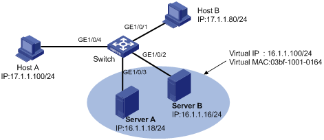
As shown in Figure 5, a small data center uses Microsoft multicast-mode NLB. To enable the switches to cooperate with NLB, configure the following:
Add GigabitEthernet 1/0/2 and GigabitEthernet 1/0/3 into VLAN 1, and specify IP address 16.1.1.30/24 for VLAN-interface 1.
Add GigabitEthernet 1/0/1 and GigabitEthernet 1/0/4 into VLAN 2, and specify IP address 17.1.1.1/24 for VLAN-interface 2.
Specify 17.1.1.1/24 as the default gateway of Host A and Host B.
Specify 16.1.1.30/24 as the default gateway of Server A and Server B.
Disable the ARP entry check function so that the switch can learn dynamic ARP entries containing multicast MAC addresses.
Configure a static multicast MAC address entry so that only interfaces GigabitEthernet 1/0/2 and GigabitEthernet 1/0/3 can receive multicast information.
Figure 5: Network diagram
Configuration procedure
This example only describes multicast ARP configuration on the switch, and is only applicable to multicast NLB. For NLB configuration on the servers, see the related documents of the Windows Server.
# Specify an IP address for VLAN-interface 2.
<Switch> system-view
[Switch] vlan 2
[Switch-vlan2] port GigabitEthernet 1/0/4
[Switch-vlan2] port GigabitEthernet 1/0/1
[Switch-vlan2] quit
[Switch] interface vlan-interface 2
[Switch-Vlan-interface2] ip address 17.1.1.1 255.255.255.0
[Switch-Vlan-interface2] quit
# Specify an IP address for VLAN-interface 1.
[Switch] interface vlan-interface 1
[Switch-Vlan-interface1] ip address 16.1.1.30 255.255.255.0
[Switch-Vlan-interface1] quit
# Disable the ARP entry check function.
[Switch] undo arp check enable
# Configure a static multicast MAC address entry.
[Switch] mac-address multicast 03bf-1001-0164 interface GigabitEthernet 1/0/2 Gigabi
tEthernet 1/0/3 vlan 1
Verifying the configuration
NLB load sharing—Enables the FTP server function of Server A and Server B. Host A and Host B send requests to the virtual IP address and each of them logs in to a different server.
NLB redundancy—Disables the network interface card of Server A. Host A and Host B send requests to the virtual IP address and both log in to the FTP server on Server B.