Static ARP entry configuration example
Network requirements
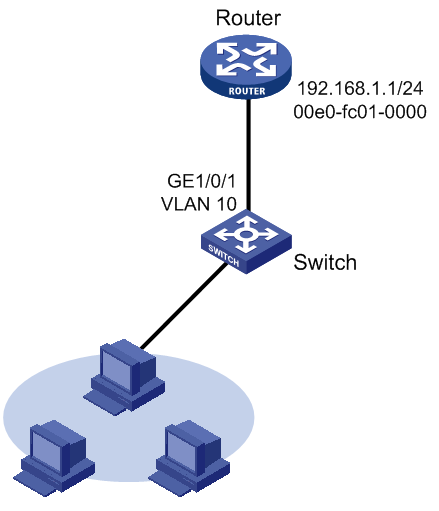
As shown in Figure 4, hosts are connected to the switch, which is connected to the router through interface GigabitEthernet 1/0/1 in VLAN 10. The IP and MAC addresses of the router are 192.168.1.1/24 and 00e0-fc01-0000 respectively.
To prevent malicious users from attacking the switch and enhance security for communications between the router and switch, configure a static ARP entry for the router on the switch.
Figure 4: Network diagram
Configuration procedure
Configure the switch:
# Create VLAN 10.
<Switch> system-view
[Switch] vlan 10
[Switch-vlan10] quit
# Add interface GigabitEthernet 1/0/1 to VLAN 10.
[Switch] interface GigabitEthernet 1/0/1
[Switch-GigabitEthernet1/0/1] port link-type trunk
[Switch-GigabitEthernet1/0/1] port trunk permit vlan 10
[Switch-GigabitEthernet1/0/1] quit
# Create interface VLAN-interface 10 and configure its IP address.
[Switch] interface vlan-interface 10
[Switch-vlan-interface10] ip address 192.168.1.2 24
[Switch-vlan-interface10] quit
# Configure a static ARP entry that has IP address 192.168.1.1, MAC address 00e0-fc01-0000, and output interface GigabitEthernet 1/0/1 in VLAN 10.
[Switch] arp static 192.168.1.1 00e0-fc01-0000 10 GigabitEthernet 1/0/1
# Display information about static ARP entries.
[Switch] display arp static
                Type: S-Static    D-Dynamic    A-Authorized
IP Address       MAC Address     VLAN ID  Interface              Aging Type
192.168.1.1      00e0-fc01-0000  10       GE1/0/1                 N/A   S