Bidirectional MPLS TE tunnel configuration example
Network requirements
Switch A, Switch B, Switch C, and Switch D all run IS-IS and they are all level-2 switches.
Use RSVP-TE to establish a bidirectional MPLS TE tunnel between Switch A and Switch D.
Figure 33: Network diagram
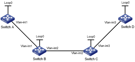
Table 5: Interface and IP address assignment
Device | Interface | IP address | Device | Interface | IP address |
|---|---|---|---|---|---|
Switch A | Loop0 | 1.1.1.9/32 | Switch D | Loop0 | 4.4.4.9/32 |
Vlan-int1 | 10.1.1.1/24 | Vlan-int3 | 30.1.1.2/24 | ||
Switch B | Loop0 | 2.2.2.9/32 | Switch C | Loop0 | 3.3.3.9/32 |
Vlan-int1 | 10.1.1.2/24 | Vlan-int3 | 30.1.1.1/24 | ||
Vlan-int2 | 20.1.1.1/24 | Vlan-int2 | 20.1.1.2/24 |
Configuration procedure
Configure IP addresses and masks for interfaces. (Details not shown.)
Configure IS-IS to advertise interface addresses, including the loopback interface address.
For more information, see "Establishing an MPLS TE tunnel with RSVP-TE."
Configure an LSR ID, and enable MPLS, MPLS TE, and RSVP-TE on each switch. Configure Switch A and Switch D to assign a non-null label to the penultimate hop:
# Configure Switch A.
<SwitchA> system-view
[SwitchA] mpls lsr-id 1.1.1.9
[SwitchA] mpls label advertise non-null
[SwitchA] mpls te
[SwitchA-te] quit
[SwitchA] rsvp
[SwitchA-rsvp] quit
[SwitchA] interface vlan-interface 1
[SwitchA-Vlan-interface1] mpls enable
[SwitchA-Vlan-interface1] mpls te enable
[SwitchA-Vlan-interface1] rsvp enable
[SwitchA-Vlan-interface1] quit
# Configure Switch B.
<SwitchB> system-view
[SwitchB] mpls lsr-id 2.2.2.9
[SwitchB] mpls te
[SwitchB-te] quit
[SwitchB] rsvp
[SwitchB-rsvp] quit
[SwitchB] interface vlan-interface 1
[SwitchB-Vlan-interface1] mpls enable
[SwitchB-Vlan-interface1] mpls te enable
[SwitchB-Vlan-interface1] rsvp enable
[SwitchB-Vlan-interface1] quit
[SwitchB] interface vlan-interface 2
[SwitchB-Vlan-interface2] mpls enable
[SwitchB-Vlan-interface2] mpls te enable
[SwitchB-Vlan-interface2] rsvp enable
[SwitchB-Vlan-interface1] quit
# Configure Switch C.
<SwitchC> system-view
[SwitchC] mpls lsr-id 3.3.3.9
[SwitchC] mpls te
[SwitchC-te] quit
[SwitchC] rsvp
[SwitchC-rsvp] quit
[SwitchC] interface vlan-interface 3
[SwitchC-Vlan-interface3] mpls enable
[SwitchC-Vlan-interface3] mpls te enable
[SwitchC-Vlan-interface3] rsvp enable
[SwitchC-Vlan-interface3] quit
[SwitchC] interface vlan-interface 2
[SwitchC-Vlan-interface2] mpls enable
[SwitchC-Vlan-interface2] mpls te enable
[SwitchC-Vlan-interface2] rsvp enable
[SwitchC-Vlan-interface2] quit
# Configure Switch D.
<SwitchD> system-view
[SwitchD] mpls lsr-id 4.4.4.9
[SwitchD] mpls label advertise non-null
[SwitchD] mpls te
[SwitchD-te] quit
[SwitchD] rsvp
[SwitchD-rsvp] quit
[SwitchD] interface vlan-interface 3
[SwitchD-Vlan-interface3] mpls enable
[SwitchD-Vlan-interface3] mpls te enable
[SwitchD-Vlan-interface3] rsvp enable
[SwitchD-Vlan-interface3] quit
Configure IS-IS TE:
# Configure Switch A.
[SwitchA] isis 1
[SwitchA-isis-1] cost-style wide
[SwitchA-isis-1] mpls te enable level-2
[SwitchA-isis-1] quit
# Configure Switch B.
[SwitchB] isis 1
[SwitchB-isis-1] cost-style wide
[SwitchB-isis-1] mpls te enable level-2
[SwitchB-isis-1] quit
# Configure Switch C.
[SwitchC] isis 1
[SwitchC-isis-1] cost-style wide
[SwitchC-isis-1] mpls te enable level-2
[SwitchC-isis-1] quit
# Configure Switch D.
[SwitchD] isis 1
[SwitchD-isis-1] cost-style wide
[SwitchD-isis-1] mpls te enable level-2
[SwitchD-isis-1] quit
Configure a co-routed bidirectional MPLS TE tunnel:
# Configure Switch A as the active end of the co-routed bidirectional tunnel.
[SwitchA] interface tunnel 1 mode mpls-te
[SwitchA-Tunnel1] ip address 7.1.1.1 255.255.255.0
[SwitchA-Tunnel1] destination 4.4.4.9
[SwitchA-Tunnel1] mpls te signaling rsvp-te
[SwitchA-Tunnel1] mpls te resv-style ff
[SwitchA-Tunnel1] mpls te bidirectional co-routed active
[SwitchA-Tunnel1] quit
# Configure Switch D as the passive end of the co-routed bidirectional tunnel.
[SwitchD] interface tunnel 4 mode mpls-te
[SwitchD-Tunnel4] ip address 8.1.1.1 255.255.255.0
[SwitchD-Tunnel4] destination 1.1.1.9
[SwitchD-Tunnel4] mpls te signaling rsvp-te
[SwitchD-Tunnel4] mpls te resv-style ff
[SwitchD-Tunnel4] mpls te bidirectional co-routed passive reverse-lsp lsr-id 1.1.1.9 tunnel-id 1
[SwitchD-Tunnel4] quit
Verifying the configuration
# Verify that the tunnel interface is up on Switch A.
[SwitchA] display interface tunnel
Tunnel1
Current state: UP
Line protocol state: UP
Description: Tunnel1 Interface
Bandwidth: 64kbps
Maximum transmission unit: 1496
Internet address: 7.1.1.1/24 (primary)
Tunnel source unknown, destination 4.4.4.9
Tunnel protocol/transport CR_LSP
Last clearing of counters: Never
Last 300 seconds input rate: 0 bytes/sec, 0 bits/sec, 0 packets/sec
Last 300 seconds output rate: 0 bytes/sec, 0 bits/sec, 0 packets/sec
Input: 0 packets, 0 bytes, 0 drops
Output: 0 packets, 0 bytes, 0 drops
# Display detailed information about the MPLS TE tunnel on Switch A.
[SwitchA] display mpls te tunnel-interface
Tunnel Name            : Tunnel 1
Tunnel State           : Up (Main CRLSP up, Reverse CRLSP up)
Tunnel Attributes      :
  LSP ID               : 30478           Tunnel ID            : 1
  Admin State          : Normal
  Ingress LSR ID       : 1.1.1.9         Egress LSR ID        : 4.4.4.9
  Signaling            : RSVP-TE         Static CRLSP Name    : -
  Resv Style           : FF
  Tunnel mode          : Co-routed, active
  Reverse-LSP name     : -
  Reverse-LSP LSR ID   : -               Reverse-LSP Tunnel ID: -
  Class Type           : CT0             Tunnel Bandwidth     : 0 kbps
  Reserved Bandwidth   : 0 kbps
  Setup Priority       : 7               Holding Priority     : 7
  Affinity Attr/Mask   : 0/0
  Explicit Path        : -
  Backup Explicit Path : -
  Metric Type          : TE
  Record Route         : Disabled        Record Label         : Disabled
  FRR Flag             : Disabled        Bandwidth Protection : Disabled
  Backup Bandwidth Flag: Disabled        Backup Bandwidth Type: -
  Backup Bandwidth     : -
  Bypass Tunnel        : No              Auto Created         : No
  Route Pinning        : Disabled
  Retry Limit          : 10              Retry Interval       : 2 sec
  Reoptimization       : Disabled        Reoptimization Freq  : -
  Backup Type          : None            Backup LSP ID        : -
  Auto Bandwidth       : Disabled        Auto Bandwidth Freq  : -
  Min Bandwidth        : -               Max Bandwidth        : -
  Collected Bandwidth  : -
# Display detailed information about the bidirectional MPLS TE tunnel on Switch A.
[SwitchA] display mpls lsp verbose
Destination  : 4.4.4.9
FEC          : 1.1.1.9/1/30478
Protocol     : RSVP
LSR Type     : Ingress
Service      : -
NHLFE ID     : 1027
State        : Active
Out-Label    : 1149
Nexthop      : 10.1.1.2
Out-Interface: Vlan1

Destination  : 4.4.4.9
FEC          : 1.1.1.9/1/30478
Protocol     : RSVP
LSR Type     : Egress
Service      : -
In-Label     : 1151
State        : Active
Nexthop      : 127.0.0.1
Out-Interface: -

Destination  : 10.1.1.2
FEC          : 10.1.1.2
Protocol     : Local
LSR Type     : Ingress
Service      : -
NHLFE ID     : 1026
State        : Active
Nexthop      : 10.1.1.2
Out-Interface: Vlan1
# Verify that the tunnel interface is up on Switch D.
[SwitchD] display interface tunnel
Tunnel4
Current state: UP
Line protocol current state: UP
Description: Tunnel4 Interface
Bandwidth: 64kbps
Maximum transmission unit: 1496
Internet address: 8.1.1.1/24 (primary)
Tunnel source unknown, destination 1.1.1.9
Tunnel TTL 255
Tunnel protocol/transport CR_LSP
Last clearing of counters: Never
Last 300 seconds input rate: 0 bytes/sec, 0 bits/sec, 0 packets/sec
Last 300 seconds output rate: 0 bytes/sec, 0 bits/sec, 0 packets/sec
Input: 0 packets input, 0 bytes, 0 drops
Output: 0 packets output, 0 bytes, 0 drops
# Display detailed information about the MPLS TE tunnel on Switch D.
[SwitchD] display mpls te tunnel-interface
Tunnel Name            : Tunnel 4
Tunnel State           : Up (Main CRLSP up, Reverse CRLSP up)
Tunnel Attributes      :
  LSP ID               : -               Tunnel ID            : 8
  Admin State          : Normal
  Ingress LSR ID       : -               Egress LSR ID        : -
  Signaling            : RSVP-TE         Static CRLSP Name    : -
  Resv Style           : FF
  Tunnel mode          : Co-routed, passive
  Reverse-LSP name     : -
  Reverse-LSP LSR ID   : 1.1.1.9         Reverse-LSP Tunnel ID: 1
  Class Type           : -               Tunnel Bandwidth     : -
  Reserved Bandwidth   : -
  Setup Priority       : -               Holding Priority     : -
  Affinity Attr/Mask   : -/-
  Explicit Path        : -
  Backup Explicit Path : -
  Metric Type          : -
  Record Route         : -               Record Label         : -
  FRR Flag             : -               Bandwidth Protection : -
  Backup Bandwidth Flag: -               Backup Bandwidth Type: -
  Backup Bandwidth     : -
  Bypass Tunnel        : -              Auto Created         : No
  Route Pinning        : -
  Retry Limit          : -               Retry Interval       : -
  Reoptimization       : -               Reoptimization Freq  : -
  Backup Type          : -               Backup LSP ID        : -
  Auto Bandwidth       : -               Auto Bandwidth Freq  : -
  Min Bandwidth        : -               Max Bandwidth        : -
  Collected Bandwidth  : -
# Display detailed information about the bidirectional MPLS TE tunnel on Switch D.
[SwitchD] display mpls lsp verbose
Destination  : 4.4.4.9
FEC          : 1.1.1.9/1/30478
Protocol     : RSVP
LSR Type     : Egress
Service      : -
In-Label     : 3
State        : Active
Nexthop      : 127.0.0.1
Out-Interface: -

Destination  : 4.4.4.9
FEC          : 1.1.1.9/1/30478
Protocol     : RSVP
LSR Type     : Ingress
Service      : -
NHLFE ID     : 1025
State        : Active
Out-Label    : 1150
Nexthop      : 30.1.1.1
Out-Interface: Vlan1

Destination  : 30.1.1.1
FEC          : 30.1.1.1
Protocol     : Local
LSR Type     : Ingress
Service      : -
NHLFE ID     : 1024
State        : Active
Nexthop      : 30.1.1.1
Out-Interface: Vlan1