Establishing an inter-area MPLS TE tunnel over a CRLSP calculated by PCEs
Network requirements
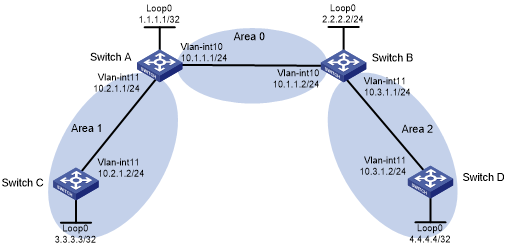
Switch A, Switch B, Switch C, and Switch D support MPLS TE and run OSPF.
Configure Switch A and Switch B as PCEs, and configure Switch C as a PCC to automatically discover the PCEs.
Establish an MPLS TE tunnel over a CRLSP from Switch C to Switch D that uses the inter-area path calculated by PCEs.
Figure 32: Network diagram
Configuration procedure
Configure IP addresses and masks for interfaces. (Details not shown.)
Configure OSPF to advertise interface addresses and configure OSPF TE:
# Configure Switch A.
<SwitchA> system-view
[SwitchA] ospf
[SwitchA-ospf-1] area 0
[SwitchA-ospf-1-area-0.0.0.0] network 10.1.1.0 0.0.0.255
[SwitchA-ospf-1-area-0.0.0.0] network 1.1.1.1 0.0.0.0
[SwitchA-ospf-1-area-0.0.0.0] mpls te enable
[SwitchA-ospf-1-area-0.0.0.0] quit
[SwitchA-ospf-1] area 1
[SwitchA-ospf-1-area-0.0.0.1] network 10.2.1.0 0.0.0.255
[SwitchA-ospf-1-area-0.0.0.1] mpls te enable
[SwitchA-ospf-1-area-0.0.0.1] quit
[SwitchA-ospf-1] quit
# Configure Switch B.
<SwitchB> system-view
[SwitchB] ospf
[SwitchB-ospf-1] area 0
[SwitchB-ospf-1-area-0.0.0.0] network 10.1.1.0 0.0.0.255
[SwitchB-ospf-1-area-0.0.0.0] network 2.2.2.2 0.0.0.0
[SwitchB-ospf-1-area-0.0.0.0] mpls te enable
[SwitchB-ospf-1-area-0.0.0.0] quit
[SwitchB-ospf-1] area 2
[SwitchB-ospf-1-area-0.0.0.2] network 10.3.1.0 0.0.0.255
[SwitchB-ospf-1-area-0.0.0.2] mpls te enable
[SwitchB-ospf-1-area-0.0.0.2] quit
[SwitchB-ospf-1] quit
# Configure Switch C.
<SwitchC> system-view
[SwitchC] ospf
[SwitchC-ospf-1] area 1
[SwitchC-ospf-1-area-0.0.0.1] network 10.2.1.0 0.0.0.255
[SwitchC-ospf-1-area-0.0.0.1] network 3.3.3.3 0.0.0.0
[SwitchC-ospf-1-area-0.0.0.1] mpls te enable
[SwitchC-ospf-1-area-0.0.0.1] quit
[SwitchC-ospf-1] quit
# Configure Switch D.
<SwitchD> system-view
[SwitchD] ospf
[SwitchD-ospf-1] area 2
[SwitchD-ospf-1-area-0.0.0.2] network 10.3.1.0 0.0.0.255
[SwitchD-ospf-1-area-0.0.0.2] network 4.4.4.4 0.0.0.0
[SwitchD-ospf-1-area-0.0.0.2] mpls te enable
[SwitchD-ospf-1-area-0.0.0.2] quit
[SwitchD-ospf-1] quit
Configure an LSR ID, and enable MPLS, MPLS TE, and RSVP-TE:
# Configure Switch A.
[SwitchA] mpls lsr-id 1.1.1.1
[SwitchA] mpls te
[SwitchA-te] quit
[SwitchA] rsvp
[SwitchA-rsvp] quit
[SwitchA] interface vlan-interface 10
[SwitchA-Vlan-interface10] mpls enable
[SwitchA-Vlan-interface10] mpls te enable
[SwitchA-Vlan-interface10] rsvp enable
[SwitchA-Vlan-interface10] quit
[SwitchA] interface vlan-interface 11
[SwitchA-Vlan-interface11] mpls enable
[SwitchA-Vlan-interface11] mpls te enable
[SwitchA-Vlan-interface11] rsvp enable
[SwitchA-Vlan-interface11] quit
# Configure Switch B.
[SwitchB] mpls lsr-id 2.2.2.2
[SwitchB] mpls te
[SwitchB-te] quit
[SwitchB] rsvp
[SwitchB-rsvp] quit
[SwitchB] interface vlan-interface 10
[SwitchB-Vlan-interface10] mpls enable
[SwitchB-Vlan-interface10] mpls te enable
[SwitchB-Vlan-interface10] rsvp enable
[SwitchB-Vlan-interface10] quit
[SwitchB] interface vlan-interface 11
[SwitchB-Vlan-interface11] mpls enable
[SwitchB-Vlan-interface11] mpls te enable
[SwitchB-Vlan-interface11] rsvp enable
[SwitchB-Vlan-interface11] quit
# Configure Switch C.
[SwitchC] mpls lsr-id 3.3.3.3
[SwitchC] mpls te
[SwitchC-te] quit
[SwitchC] rsvp
[SwitchC-rsvp] quit
[SwitchC] interface vlan-interface 11
[SwitchC-Vlan-interface11] mpls enable
[SwitchC-Vlan-interface11] mpls te enable
[SwitchC-Vlan-interface11] rsvp enable
[SwitchC-Vlan-interface11] quit
# Configure Switch D.
[SwitchD] mpls lsr-id 4.4.4.4
[SwitchD] mpls te
[SwitchD-te] quit
[SwitchD] rsvp
[SwitchD-rsvp] quit
[SwitchD] interface vlan-interface 11
[SwitchD-Vlan-interface11] mpls enable
[SwitchD-Vlan-interface11] mpls te enable
[SwitchD-Vlan-interface11] rsvp enable
[SwitchD-Vlan-interface11] quit
Configure Switch A and Switch B as PCEs:
# Configure Switch A.
[SwitchA] mpls te
[SwitchA-te] pce address 1.1.1.1
# Configure Switch B.
[SwitchB] mpls te
[SwitchB-te] pce address 2.2.2.2
Configure Switch C as a PCC to use the path calculated by PCEs:
# Configure MPLS TE tunnel interface Tunnel 1.
[SwitchC] interface tunnel 1 mode mpls-te
[SwitchC-Tunnel1] ip address 7.1.1.1 255.255.255.0
# Specify the tunnel destination address as the LSR ID of Switch D.
[SwitchC-Tunnel1] destination 4.4.4.4
# Configure MPLS TE to use RSVP-TE to establish the tunnel.
[SwitchC-Tunnel1] mpls te signaling rsvp-te
# Assign 2000 kbps bandwidth to the tunnel.
[SwitchC-Tunnel1] mpls te bandwidth 2000
# Configure the tunnel to use the path calculated by PCEs.
[SwitchC-Tunnel1] mpls te path preference 2 dynamic pce 1.1.1.1 2.2.2.2
[SwitchC-Tunnel1] quit
Verifying the configuration
# Display discovered PCE information on each switch. This example uses Switch A.
[SwitchA] display mpls te pce discovery verbose
PCE address: 2.2.2.2
  Discovery methods: OSPF
  Path scopes:
    Path scope                                                Preference
    Compute intra-area paths                                  7
    Act as PCE for inter-area TE LSP computation              6
    Act as a default PCE for inter-area TE LSP computation    6
  Capabilities:
    Bidirectional path computation
    Support for request prioritization
    Support for multiple requests per message
  Domains:
    OSPF 1 area 0.0.0.0
    OSPF 1 area 0.0.0.2
# Verify that PCEP sessions have been established on each switch. This example uses Switch A.
[SwitchA] display mpls te pce peer verbose
Peer address: 2.2.2.2
  TCP connection          : 1.1.1.1:29507 -> 2.2.2.2:4189
  Peer type               : PCE
  Session type            : Stateless
  Session state           : UP
  Mastership              : Normal
  Role                    : Active
  Session up time         : 0000 days 00 hours 00 minutes
  Session ID              : Local 0, Peer 0
  Keepalive interval      : Local 30 sec, Peer 30 sec
  Recommended DeadTimer   : Local 120 sec, Peer 120 sec
  Tolerance:
    Min keepalive interval: 10 sec
    Max unknown messages  : 5
  Request timeout         : 10 sec
  Delegation timeout      : 30 sec

Peer address: 3.3.3.3
  TCP connection          : 3.3.3.3:29507 -> 1.1.1.1:4189
  Peer type               : PCC
  Session type            : Stateless
  Session state           : UP
  Mastership              : Normal
  Role                    : Active
  Session up time         : 0000 days 00 hours 00 minutes
  Session ID              : Local 2, Peer 0
  Keepalive interval      : Local 30 sec, Peer 30 sec
  Recommended DeadTimer   : Local 120 sec, Peer 120 sec
  Tolerance:
    Min keepalive interval: 10 sec
    Max unknown messages  : 5
  Request timeout         : 10 sec
  Delegation timeout      : 30 sec