Establishing an MPLS TE tunnel with RSVP-TE
Network requirements
Switch A, Switch B, Switch C, and Switch D run IS-IS and all of them are Level-2 switches.
Use RSVP-TE to establish an MPLS TE tunnel from Switch A to Switch D to transmit data between the two IP networks. The MPLS TE tunnel requires a bandwidth of 2000 kbps.
The maximum bandwidth of the link that the tunnel traverses is 10000 kbps and the maximum reservable bandwidth of the link is 5000 kbps.
Figure 30: Network diagram
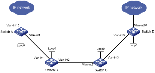
Table 3: Interface and IP address assignment
Device | Interface | IP address | Device | Interface | IP address |
|---|---|---|---|---|---|
Switch A | Loop0 | 1.1.1.9/32 | Switch D | Loop0 | 4.4.4.9/32 |
Vlan-int1 | 10.1.1.1/24 | Vlan-int3 | 30.1.1.2/24 | ||
Vlan-int10 | 100.1.1.1/24 | Vlan-int10 | 100.1.2.1/24 | ||
Switch B | Loop0 | 2.2.2.9/32 | Switch C | Loop0 | 3.3.3.9/32 |
Vlan-int1 | 10.1.1.2/24 | Vlan-int3 | 30.1.1.1/24 | ||
Vlan-int2 | 20.1.1.1/24 | Vlan-int2 | 20.1.1.2/24 |
Configuration procedure
Configure IP addresses and masks for interfaces. (Details not shown.)
Configure IS-IS to advertise interface addresses, including the loopback interface address:
# Configure Switch A.
<SwitchA> system-view
[SwitchA] isis 1
[SwitchA-isis-1] network-entity 00.0005.0000.0000.0001.00
[SwitchA-isis-1] quit
[SwitchA] interface vlan-interface 1
[SwitchA-Vlan-interface1] isis enable 1
[SwitchA-Vlan-interface1] isis circuit-level level-2
[SwitchA-Vlan-interface1] quit
[SwitchA] interface loopback 0
[SwitchA-LoopBack0] isis enable 1
[SwitchA-LoopBack0] isis circuit-level level-2
[SwitchA-LoopBack0] quit
# Configure Switch B.
<SwitchB> system-view
[SwitchB] isis 1
[SwitchB-isis-1] network-entity 00.0005.0000.0000.0002.00
[SwitchB-isis-1] quit
[SwitchB] interface vlan-interface 1
[SwitchB-Vlan-interface1] isis enable 1
[SwitchB-Vlan-interface1] isis circuit-level level-2
[SwitchB-Vlan-interface1] quit
[SwitchB] interface vlan-interface 2
[SwitchB-Vlan-interface2] isis enable 1
[SwitchB-Vlan-interface2] isis circuit-level level-2
[SwitchB-Vlan-interface2] quit
[SwitchB] interface loopback 0
[SwitchB-LoopBack0] isis enable 1
[SwitchB-LoopBack0] isis circuit-level level-2
[SwitchB-LoopBack0] quit
# Configure Switch C.
<SwitchC> system-view
[SwitchC] isis 1
[SwitchC-isis-1] network-entity 00.0005.0000.0000.0003.00
[SwitchC-isis-1] quit
[SwitchC] interface vlan-interface 3
[SwitchC-Vlan-interface3] isis enable 1
[SwitchC-Vlan-interface3] isis circuit-level level-2
[SwitchC-Vlan-interface3] quit
[SwitchC] interface vlan-interface 2
[SwitchC-Vlan-interface2] isis enable 1
[SwitchC-Vlan-interface2] isis circuit-level level-2
[SwitchC-Vlan-interface2] quit
[SwitchC] interface loopback 0
[SwitchC-LoopBack0] isis enable 1
[SwitchC-LoopBack0] isis circuit-level level-2
[SwitchC-LoopBack0] quit
# Configure Switch D.
<SwitchD> system-view
[SwitchD] isis 1
[SwitchD-isis-1] network-entity 00.0005.0000.0000.0004.00
[SwitchD-isis-1] quit
[SwitchD] interface vlan-interface 3
[SwitchD-Vlan-interface3] isis enable 1
[SwitchD-Vlan-interface3] isis circuit-level level-2
[SwitchD-Vlan-interface3] quit
[SwitchD] interface loopback 0
[SwitchD-LoopBack0] isis enable 1
[SwitchD-LoopBack0] isis circuit-level level-2
[SwitchD-LoopBack0] quit
# Execute the display ip routing-table command on each switch to verify that the switches have learned the routes to one another, including the routes to the loopback interfaces. (Details not shown.)
Configure an LSR ID, and enable MPLS, MPLS TE, and RSVP-TE:
# Configure Switch A.
[SwitchA] mpls lsr-id 1.1.1.9
[SwitchA] mpls te
[SwitchA-te] quit
[SwitchA] rsvp
[SwitchA-rsvp] quit
[SwitchA] interface vlan-interface 1
[SwitchA-Vlan-interface1] mpls enable
[SwitchA-Vlan-interface1] mpls te enable
[SwitchA-Vlan-interface1] rsvp enable
[SwitchA-Vlan-interface1] quit
# Configure Switch B.
[SwitchB] mpls lsr-id 2.2.2.9
[SwitchB] mpls te
[SwitchB-te] quit
[SwitchB] rsvp
[SwitchB-rsvp] quit
[SwitchB] interface vlan-interface 1
[SwitchB-Vlan-interface1] mpls enable
[SwitchB-Vlan-interface1] mpls te enable
[SwitchB-Vlan-interface1] rsvp enable
[SwitchB-Vlan-interface1] quit
[SwitchB] interface vlan-interface 2
[SwitchB-Vlan-interface2] mpls enable
[SwitchB-Vlan-interface2] mpls te enable
[SwitchB-Vlan-interface2] rsvp enable
[SwitchB-Vlan-interface2] quit
# Configure Switch C.
[SwitchC] mpls lsr-id 3.3.3.9
[SwitchC] mpls te
[SwitchC-te] quit
[SwitchC] rsvp
[SwitchC-rsvp] quit
[SwitchC] interface vlan-interface 3
[SwitchC-Vlan-interface3] mpls enable
[SwitchC-Vlan-interface3] mpls te enable
[SwitchC-Vlan-interface3] rsvp enable
[SwitchC-Vlan-interface3] quit
[SwitchC] interface vlan-interface 2
[SwitchC-Vlan-interface2] mpls enable
[SwitchC-Vlan-interface2] mpls te enable
[SwitchC-Vlan-interface2] rsvp enable
[SwitchC-Vlan-interface2] quit
# Configure Switch D.
[SwitchD] mpls lsr-id 4.4.4.9
[SwitchD] mpls te
[SwitchD-te] quit
[SwitchD] rsvp
[SwitchD-rsvp] quit
[SwitchD] interface vlan-interface 3
[SwitchD-Vlan-interface3] mpls enable
[SwitchD-Vlan-interface3] mpls te enable
[SwitchD-Vlan-interface3] rsvp enable
[SwitchD-Vlan-interface3] quit
Configure IS-IS TE:
# Configure Switch A.
[SwitchA] isis 1
[SwitchA-isis-1] cost-style wide
[SwitchA-isis-1] mpls te enable level-2
[SwitchA-isis-1] quit
# Configure Switch B.
[SwitchB] isis 1
[SwitchB-isis-1] cost-style wide
[SwitchB-isis-1] mpls te enable level-2
[SwitchB-isis-1] quit
# Configure Switch C.
[SwitchC] isis 1
[SwitchC-isis-1] cost-style wide
[SwitchC-isis-1] mpls te enable level-2
[SwitchC-isis-1] quit
# Configure Switch D.
[SwitchD] isis 1
[SwitchD-isis-1] cost-style wide
[SwitchD-isis-1] mpls te enable level-2
[SwitchD-isis-1] quit
Configure MPLS TE attributes of links:
# Set the maximum link bandwidth and maximum reservable bandwidth on Switch A.
[SwitchA] interface vlan-interface 1
[SwitchA-Vlan-interface1] mpls te max-link-bandwidth 10000
[SwitchA-Vlan-interface1] mpls te max-reservable-bandwidth 5000
[SwitchA-Vlan-interface1] quit
# Set the maximum link bandwidth and maximum reservable bandwidth on Switch B.
[SwitchB] interface vlan-interface 1
[SwitchB-Vlan-interface1] mpls te max-link-bandwidth 10000
[SwitchB-Vlan-interface1] mpls te max-reservable-bandwidth 5000
[SwitchB-Vlan-interface1] quit
[SwitchB] interface vlan-interface 2
[SwitchB-Vlan-interface2] mpls te max-link-bandwidth 10000
[SwitchB-Vlan-interface2] mpls te max-reservable-bandwidth 5000
[SwitchB-Vlan-interface2] quit
# Set the maximum link bandwidth and maximum reservable bandwidth on Switch C.
[SwitchC] interface vlan-interface 3
[SwitchC-Vlan-interface3] mpls te max-link-bandwidth 10000
[SwitchC-Vlan-interface3] mpls te max-reservable-bandwidth 5000
[SwitchC-Vlan-interface3] quit
[SwitchC] interface vlan-interface 2
[SwitchC-Vlan-interface2] mpls te max-link-bandwidth 10000
[SwitchC-Vlan-interface2] mpls te max-reservable-bandwidth 5000
[SwitchC-Vlan-interface2] quit
# Set the maximum link bandwidth and maximum reservable bandwidth on Switch D.
[SwitchD] interface vlan-interface 3
[SwitchD-Vlan-interface3] mpls te max-link-bandwidth 10000
[SwitchD-Vlan-interface3] mpls te max-reservable-bandwidth 5000
[SwitchD-Vlan-interface3] quit
Configure an MPLS TE tunnel on Switch A:
# Configure MPLS TE tunnel interface Tunnel 1.
[SwitchA] interface tunnel 1 mode mpls-te
[SwitchA-Tunnel1] ip address 7.1.1.1 255.255.255.0
# Specify the tunnel destination address as the LSR ID of Switch D.
[SwitchA-Tunnel1] destination 4.4.4.9
# Configure MPLS TE to use RSVP-TE to establish the tunnel.
[SwitchA-Tunnel1] mpls te signaling rsvp-te
# Assign 2000 kbps bandwidth to the tunnel.
[SwitchA-Tunnel1] mpls te bandwidth 2000
[SwitchA-Tunnel1] quit
Configure a static route on Switch A to direct the traffic destined for subnet 100.1.2.0/24 to MPLS TE tunnel 1.
[SwitchA] ip route-static 100.1.2.0 24 tunnel 1 preference 1
Verifying the configuration
# Verify that the tunnel interface is up on Switch A.
[SwitchA] display interface tunnel
Tunnel1
Current state: UP
Line protocol state: UP
Description: Tunnel1 Interface
Bandwidth: 64kbps
Maximum transmission unit: 1496
Internet address: 7.1.1.1/24 (primary)
Tunnel source unknown, destination 4.4.4.9
Tunnel TTL 255
Tunnel protocol/transport CR_LSP
Last clearing of counters: Never
Last 300 seconds input rate: 0 bytes/sec, 0 bits/sec, 0 packets/sec
Last 300 seconds output rate: 6 bytes/sec, 48 bits/sec, 0 packets/sec
Input: 0 packets, 0 bytes, 0 drops
Output: 177 packets, 11428 bytes, 0 drops
# Display detailed information about the MPLS TE tunnel on Switch A.
[SwitchA] display mpls te tunnel-interface
Tunnel Name            : Tunnel 1
Tunnel State           : Up (Main CRLSP up, Shared-resource CRLSP down)
Tunnel Attributes      :
  LSP ID               : 23331           Tunnel ID            : 1
  Admin State          : Normal
  Ingress LSR ID       : 1.1.1.9         Egress LSR ID        : 4.4.4.9
  Signaling            : RSVP-TE         Static CRLSP Name    : -
  Resv Style           : SE
  Tunnel mode          : -
  Reverse-LSP name     : -
  Reverse-LSP LSR ID   : -               Reverse-LSP Tunnel ID: -
  Class Type           : CT0             Tunnel Bandwidth     : 2000 kbps
  Reserved Bandwidth   : 2000 kbps
  Setup Priority       : 7               Holding Priority     : 7
  Affinity Attr/Mask   : 0/0
  Explicit Path        : -
  Backup Explicit Path : -
  Metric Type          : TE
  Record Route         : Disabled        Record Label         : Disabled
  FRR Flag             : Disabled        Bandwidth Protection : Disabled
  Backup Bandwidth Flag: Disabled        Backup Bandwidth Type: -
  Backup Bandwidth     : -
  Bypass Tunnel        : No               Auto Created         : No
  Route Pinning        : Disabled
  Retry Limit          : 10              Retry Interval       : 2 sec
  Reoptimization       : Disabled        Reoptimization Freq  : -
  Backup Type          : None            Backup LSP ID        : -
  Auto Bandwidth       : Disabled        Auto Bandwidth Freq  : -
  Min Bandwidth        : -               Max Bandwidth        : -
  Collected Bandwidth  : -
# Execute the display ip routing-table command on Switch A. The output shows a static route entry with interface Tunnel 1 as the output interface. (Details not shown.)