Label acceptance control configuration example
Network requirements
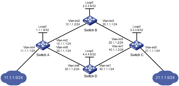
Two links, Switch A—Switch B—Switch C and Switch A—Switch D—Switch C, exist between subnets 11.1.1.0/24 and 21.1.1.0/24.
Configure LDP to establish LSPs only for routes to subnets 11.1.1.0/24 and 21.1.1.0/24.
Configure LDP to establish LSPs only on the link Switch A—Switch B—Switch C to forward traffic between subnets 11.1.1.0/24 and 21.1.1.0/24.
Figure 19: Network diagram
Requirements analysis
To ensure that the LSRs establish IPv4 LSPs automatically, enable IPv4 LDP on each LSR.
To establish IPv4 LDP LSPs, configure an IPv4 routing protocol to ensure IP connectivity between the LSRs. This example uses OSPF.
To ensure that LDP establishes IPv4 LSPs only for the routes 11.1.1.0/24 and 21.1.1.0/24, configure IPv4 LSP generation policies on each LSR.
To ensure that LDP establishes IPv4 LSPs only over the link Switch A—Switch B—Switch C, configure IPv4 label acceptance policies as follows:
Switch A accepts only the label mapping for FEC 21.1.1.0/24 received from Switch B. Switch A denies the label mapping for FEC 21.1.1.0/24 received from Switch D.
Switch C accepts only the label mapping for FEC 11.1.1.0/24 received from Switch B. Switch C denies the label mapping for FEC 11.1.1.0/24 received from Switch D.
Configuration procedure
Before configuration, disable the spanning tree feature globally or map each VLAN to an MSTI. For more information, see Layer 2—LAN Switching Configuration Guide.
Configure IP addresses and masks for interfaces, including the loopback interfaces, as shown in Figure 19. (Details not shown.)
Configure OSPF on each switch to ensure IP connectivity between them. (Details not shown.)
Enable MPLS and IPv4 LDP:
# Configure Switch A.
<SwitchA> system-view
[SwitchA] mpls lsr-id 1.1.1.9
[SwitchA] mpls ldp
[SwitchA-ldp] quit
[SwitchA] interface vlan-interface 2
[SwitchA-Vlan-interface2] mpls enable
[SwitchA-Vlan-interface2] mpls ldp enable
[SwitchA-Vlan-interface2] quit
[SwitchA] interface vlan-interface 6
[SwitchA-Vlan-interface6] mpls enable
[SwitchA-Vlan-interface6] mpls ldp enable
[SwitchA-Vlan-interface6] quit
# Configure Switch B.
<SwitchB> system-view
[SwitchB] mpls lsr-id 2.2.2.9
[SwitchB] mpls ldp
[SwitchB-ldp] quit
[SwitchB] interface vlan-interface 2
[SwitchB-Vlan-interface2] mpls enable
[SwitchB-Vlan-interface2] mpls ldp enable
[SwitchB-Vlan-interface2] quit
[SwitchB] interface vlan-interface 3
[SwitchB-Vlan-interface3] mpls enable
[SwitchB-Vlan-interface3] mpls ldp enable
[SwitchB-Vlan-interface3] quit
# Configure Switch C.
<SwitchC> system-view
[SwitchC] mpls lsr-id 3.3.3.9
[SwitchC] mpls ldp
[SwitchC-ldp] quit
[SwitchC] interface vlan-interface 3
[SwitchC-Vlan-interface3] mpls enable
[SwitchC-Vlan-interface3] mpls ldp enable
[SwitchC-Vlan-interface3] quit
[SwitchC] interface vlan-interface 7
[SwitchC-Vlan-interface7] mpls enable
[SwitchC-Vlan-interface7] mpls ldp enable
[SwitchC-Vlan-interface7] quit
# Configure Switch D.
<SwitchD> system-view
[SwitchD] mpls lsr-id 4.4.4.9
[SwitchD] mpls ldp
[SwitchD-ldp] quit
[SwitchD] interface vlan-interface 6
[SwitchD-Vlan-interface6] mpls enable
[SwitchD-Vlan-interface6] mpls ldp enable
[SwitchD-Vlan-interface6] quit
[SwitchD] interface vlan-interface 7
[SwitchD-Vlan-interface7] mpls enable
[SwitchD-Vlan-interface7] mpls ldp enable
[SwitchD-Vlan-interface7] quit
Configure IPv4 LSP generation policies:
# On Switch A, create IP prefix list switcha, and configure LDP to use only the routes permitted by the prefix list to establish LSPs.
[SwitchA] ip prefix-list switcha index 10 permit 11.1.1.0 24
[SwitchA] ip prefix-list switcha index 20 permit 21.1.1.0 24
[SwitchA] mpls ldp
[SwitchA-ldp] lsp-trigger prefix-list switcha
[SwitchA-ldp] quit
# On Switch B, create IP prefix list switchb, and configure LDP to use only the routes permitted by the prefix list to establish LSPs.
[SwitchB] ip prefix-list switchb index 10 permit 11.1.1.0 24
[SwitchB] ip prefix-list switchb index 20 permit 21.1.1.0 24
[SwitchB] mpls ldp
[SwitchB-ldp] lsp-trigger prefix-list switchb
[SwitchB-ldp] quit
# On Switch C, create IP prefix list switchc, and configure LDP to use only the routes permitted by the prefix list to establish LSPs.
[SwitchC] ip prefix-list switchc index 10 permit 11.1.1.0 24
[SwitchC] ip prefix-list switchc index 20 permit 21.1.1.0 24
[SwitchC] mpls ldp
[SwitchC-ldp] lsp-trigger prefix-list switchc
[SwitchC-ldp] quit
# On Switch D, create IP prefix list switchd, and configure LDP to use only the routes permitted by the prefix list to establish LSPs.
[SwitchD] ip prefix-list switchd index 10 permit 11.1.1.0 24
[SwitchD] ip prefix-list switchd index 20 permit 21.1.1.0 24
[SwitchD] mpls ldp
[SwitchD-ldp] lsp-trigger prefix-list switchd
[SwitchD-ldp] quit
Configure IPv4 label acceptance policies:
# On Switch A, create IP prefix list prefix-from-b to permit subnet 21.1.1.0/24. Switch A uses this list to filter FEC-label mappings received from Switch B.
[SwitchA] ip prefix-list prefix-from-b index 10 permit 21.1.1.0 24
# On Switch A, create IP prefix list prefix-from-d to deny subnet 21.1.1.0/24. Switch A uses this list to filter FEC-label mappings received from Switch D.
[SwitchA] ip prefix-list prefix-from-d index 10 deny 21.1.1.0 24
# On Switch A, configure label acceptance policies to filter FEC-label mappings received from Switch B and Switch D.
[SwitchA] mpls ldp
[SwitchA-ldp] accept-label peer 2.2.2.9 prefix-list prefix-from-b
[SwitchA-ldp] accept-label peer 4.4.4.9 prefix-list prefix-from-d
[SwitchA-ldp] quit
# On Switch C, create IP prefix list prefix-from-b to permit subnet 11.1.1.0/24. Switch C uses this list to filter FEC-label mappings received from Switch B.
[SwitchC] ip prefix-list prefix-from-b index 10 permit 11.1.1.0 24
# On Switch C, create IP prefix list prefix-from-d to deny subnet 11.1.1.0/24. Switch A uses this list to filter FEC-label mappings received from Switch D.
[SwitchC] ip prefix-list prefix-from-d index 10 deny 11.1.1.0 24
# On Switch C, configure label acceptance policies to filter FEC-label mappings received from Switch B and Switch D.
[SwitchC] mpls ldp
[SwitchC-ldp] accept-label peer 2.2.2.9 prefix-list prefix-from-b
[SwitchC-ldp] accept-label peer 4.4.4.9 prefix-list prefix-from-d
[SwitchC-ldp] quit
Verifying the configuration
# Display LDP LSP information on the switches, for example, on Switch A.
[SwitchA] display mpls ldp lsp
Status Flags: * - stale, L - liberal, B - backup
FECs: 2            Ingress: 1          Transit: 1      Egress: 1

FEC                In/Out Label        Nexthop         OutInterface
11.1.1.0/24        1277/-
                   -/1148(L)
21.1.1.0/24        -/1149(L)
                   -/1276              10.1.1.2        Vlan-int2
                   1276/1276           10.1.1.2        Vlan-int2
The output shows that the next hop of the LSP for FEC 21.1.1.0/24 is Switch B (10.1.1.2). The LSP has been established over the link Switch A—Switch B—Switch C, not over the link Switch A—Switch D—Switch C.
# Test the connectivity of the LDP LSP from Switch A to Switch C.
[SwitchA] ping mpls -a 11.1.1.1 ipv4 21.1.1.0 24
MPLS Ping FEC: 21.1.1.0/24 : 100 data bytes
100 bytes from 20.1.1.2: Sequence=1 time=1 ms
100 bytes from 20.1.1.2: Sequence=2 time=1 ms
100 bytes from 20.1.1.2: Sequence=3 time=8 ms
100 bytes from 20.1.1.2: Sequence=4 time=2 ms
100 bytes from 20.1.1.2: Sequence=5 time=1 ms

--- FEC: 21.1.1.0/24 ping statistics ---
5 packets transmitted, 5 packets received, 0.0% packet loss
round-trip min/avg/max = 1/2/8 ms
# Test the connectivity of the LDP LSP from Switch C to Switch A.
[SwitchC] ping mpls -a 21.1.1.1 ipv4 11.1.1.0 24
MPLS Ping FEC: 11.1.1.0/24 : 100 data bytes
100 bytes from 10.1.1.1: Sequence=1 time=1 ms
100 bytes from 10.1.1.1: Sequence=2 time=1 ms
100 bytes from 10.1.1.1: Sequence=3 time=1 ms
100 bytes from 10.1.1.1: Sequence=4 time=1 ms
100 bytes from 10.1.1.1: Sequence=5 time=1 ms

--- FEC: 11.1.1.0/24 ping statistics ---
5 packets transmitted, 5 packets received, 0.0% packet loss
round-trip min/avg/max = 1/1/1 ms