LDP LSP configuration example
Network requirements
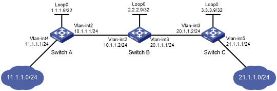
Switch A, Switch B, and Switch C all support MPLS.
Configure LDP to establish LSPs between Switch A and Switch C, so subnets 11.1.1.0/24 and 21.1.1.0/24 can reach each other over MPLS.
Configure LDP to establish LSPs only for destinations 1.1.1.9/32, 2.2.2.9/32, 3.3.3.9/32, 11.1.1.0/24, and 21.1.1.0/24 on Switch A, Switch B, and Switch C.
Figure 18: Network diagram
Requirements analysis
To ensure that the LSRs establish IPv4 LSPs automatically, enable IPv4 LDP on each LSR.
To establish IPv4 LDP LSPs, configure an IPv4 routing protocol to ensure IP connectivity between the LSRs. This example uses OSPF.
To control the number of IPv4 LSPs, configure an IPv4 LSP generation policy on each LSR.
Configuration procedure
Configure IP addresses and masks for interfaces, including the loopback interfaces, as shown in Figure 18. (Details not shown.)
Configure OSPF on each switch to ensure IP connectivity between them:
# Configure Switch A.
<SwitchA> system-view
[SwitchA] ospf
[SwitchA-ospf-1] area 0
[SwitchA-ospf-1-area-0.0.0.0] network 1.1.1.9 0.0.0.0
[SwitchA-ospf-1-area-0.0.0.0] network 10.1.1.0 0.0.0.255
[SwitchA-ospf-1-area-0.0.0.0] network 11.1.1.0 0.0.0.255
[SwitchA-ospf-1-area-0.0.0.0] quit
[SwitchA-ospf-1] quit
# Configure Switch B.
<SwitchB> system-view
[SwitchB] ospf
[SwitchB-ospf-1] area 0
[SwitchB-ospf-1-area-0.0.0.0] network 2.2.2.9 0.0.0.0
[SwitchB-ospf-1-area-0.0.0.0] network 10.1.1.0 0.0.0.255
[SwitchB-ospf-1-area-0.0.0.0] network 20.1.1.0 0.0.0.255
[SwitchB-ospf-1-area-0.0.0.0] quit
[SwitchB-ospf-1] quit
# Configure Switch C.
<SwitchC> system-view
[SwitchC] ospf
[SwitchC-ospf-1] area 0
[SwitchC-ospf-1-area-0.0.0.0] network 3.3.3.9 0.0.0.0
[SwitchC-ospf-1-area-0.0.0.0] network 20.1.1.0 0.0.0.255
[SwitchC-ospf-1-area-0.0.0.0] network 21.1.1.0 0.0.0.255
[SwitchC-ospf-1-area-0.0.0.0] quit
[SwitchC-ospf-1] quit
# Verify that the switches have learned the routes to each other. This example uses Switch A.
[SwitchA] display ip routing-table

Destinations : 21        Routes : 21

Destination/Mask   Proto   Pre Cost        NextHop         Interface
0.0.0.0/32         Direct  0   0           127.0.0.1       InLoop0
1.1.1.9/32         Direct  0   0           127.0.0.1       InLoop0
2.2.2.9/32         O_INTRA 10  1           10.1.1.2        Vlan2
3.3.3.9/32         O_INTRA 10  2           10.1.1.2        Vlan2
10.1.1.0/24        Direct  0   0           10.1.1.1        Vlan2
10.1.1.0/32        Direct  0   0           10.1.1.1        Vlan2
10.1.1.1/32        Direct  0   0           127.0.0.1       InLoop0
10.1.1.255/32      Direct  0   0           10.1.1.1        Vlan2
11.1.1.0/24        Direct  0   0           11.1.1.1        Vlan4
11.1.1.0/32        Direct  0   0           11.1.1.1        Vlan4
11.1.1.1/32        Direct  0   0           127.0.0.1       InLoop0
11.1.1.255/32      Direct  0   0           11.1.1.1        Vlan4
20.1.1.0/24        OSPF    10  2           10.1.1.2        Vlan2
21.1.1.0/24        OSPF    10  3           10.1.1.2        Vlan2
127.0.0.0/8        Direct  0   0           127.0.0.1       InLoop0
127.0.0.0/32       Direct  0   0           127.0.0.1       InLoop0
127.0.0.1/32       Direct  0   0           127.0.0.1       InLoop0
127.255.255.255/32 Direct  0   0           127.0.0.1       InLoop0
224.0.0.0/4        Direct  0   0           0.0.0.0         NULL0
224.0.0.0/24       Direct  0   0           0.0.0.0         NULL0
255.255.255.255/32 Direct  0   0           127.0.0.1       InLoop0
Enable MPLS and IPv4 LDP:
# Configure Switch A.
[SwitchA] mpls lsr-id 1.1.1.9
[SwitchA] mpls ldp
[SwitchA-ldp] quit
[SwitchA] interface vlan-interface 2
[SwitchA-Vlan-interface2] mpls enable
[SwitchA-Vlan-interface2] mpls ldp enable
[SwitchA-Vlan-interface2] quit
# Configure Switch B.
[SwitchB] mpls lsr-id 2.2.2.9
[SwitchB] mpls ldp
[SwitchB-ldp] quit
[SwitchB] interface vlan-interface 2
[SwitchB-Vlan-interface2] mpls enable
[SwitchB-Vlan-interface2] mpls ldp enable
[SwitchB-Vlan-interface2] quit
[SwitchB] interface vlan-interface 3
[SwitchB-Vlan-interface3] mpls enable
[SwitchB-Vlan-interface3] mpls ldp enable
[SwitchB-Vlan-interface3] quit
# Configure Switch C.
[SwitchC] mpls lsr-id 3.3.3.9
[SwitchC] mpls ldp
[SwitchC-ldp] quit
[SwitchC] interface vlan-interface 3
[SwitchC-Vlan-interface3] mpls enable
[SwitchC-Vlan-interface3] mpls ldp enable
[SwitchC-Vlan-interface3] quit
Configure IPv4 LSP generation policies:
# On Switch A, create IP prefix list switcha, and configure LDP to use only the routes permitted by the prefix list to establish LSPs.
[SwitchA] ip prefix-list switcha index 10 permit 1.1.1.9 32
[SwitchA] ip prefix-list switcha index 20 permit 2.2.2.9 32
[SwitchA] ip prefix-list switcha index 30 permit 3.3.3.9 32
[SwitchA] ip prefix-list switcha index 40 permit 11.1.1.0 24
[SwitchA] ip prefix-list switcha index 50 permit 21.1.1.0 24
[SwitchA] mpls ldp
[SwitchA-ldp] lsp-trigger prefix-list switcha
[SwitchA-ldp] quit
# On Switch B, create IP prefix list switchb, and configure LDP to use only the routes permitted by the prefix list to establish LSPs.
[SwitchB] ip prefix-list switchb index 10 permit 1.1.1.9 32
[SwitchB] ip prefix-list switchb index 20 permit 2.2.2.9 32
[SwitchB] ip prefix-list switchb index 30 permit 3.3.3.9 32
[SwitchB] ip prefix-list switchb index 40 permit 11.1.1.0 24
[SwitchB] ip prefix-list switchb index 50 permit 21.1.1.0 24
[SwitchB] mpls ldp
[SwitchB-ldp] lsp-trigger prefix-list switchb
[SwitchB-ldp] quit
# On Switch C, create IP prefix list switchc, and configure LDP to use only the routes permitted by the prefix list to establish LSPs.
[SwitchC] ip prefix-list switchc index 10 permit 1.1.1.9 32
[SwitchC] ip prefix-list switchc index 20 permit 2.2.2.9 32
[SwitchC] ip prefix-list switchc index 30 permit 3.3.3.9 32
[SwitchC] ip prefix-list switchc index 40 permit 11.1.1.0 24
[SwitchC] ip prefix-list switchc index 50 permit 21.1.1.0 24
[SwitchC] mpls ldp
[SwitchC-ldp] lsp-trigger prefix-list switchc
[SwitchC-ldp] quit
Verifying the configuration
# Display LDP LSP information on the switches, for example, on Switch A.
[SwitchA] display mpls ldp lsp
Status Flags: * - stale, L - liberal, B - backup
FECs: 5            Ingress: 3          Transit: 3      Egress: 2

FEC                In/Out Label        Nexthop         OutInterface
1.1.1.9/32         3/-
                   -/1279(L)
2.2.2.9/32         -/3                 10.1.1.2        Vlan-int2
                   1279/3              10.1.1.2        Vlan-int2
3.3.3.9/32         -/1278              10.1.1.2        Vlan-int2
                   1278/1278           10.1.1.2        Vlan-int2
11.1.1.0/24        1277/-
                   -/1277(L)
21.1.1.0/24        -/1276              10.1.1.2        Vlan-int2
                   1276/1276           10.1.1.2        Vlan-int2
# Test the connectivity of the LDP LSP from Switch A to Switch C.
[SwitchA] ping mpls -a 11.1.1.1 ipv4 21.1.1.0 24
MPLS Ping FEC: 21.1.1.0/24 : 100 data bytes
100 bytes from 20.1.1.2: Sequence=1 time=1 ms
100 bytes from 20.1.1.2: Sequence=2 time=1 ms
100 bytes from 20.1.1.2: Sequence=3 time=8 ms
100 bytes from 20.1.1.2: Sequence=4 time=2 ms
100 bytes from 20.1.1.2: Sequence=5 time=1 ms

--- FEC: 21.1.1.0/24 ping statistics ---
5 packets transmitted, 5 packets received, 0.0% packet loss
round-trip min/avg/max = 1/2/8 ms
# Test the connectivity of the LDP LSP from Switch C to Switch A.
[SwitchC] ping mpls -a 21.1.1.1 ipv4 11.1.1.0 24
MPLS Ping FEC: 11.1.1.0/24 : 100 data bytes
100 bytes from 10.1.1.1: Sequence=1 time=1 ms
100 bytes from 10.1.1.1: Sequence=2 time=1 ms
100 bytes from 10.1.1.1: Sequence=3 time=1 ms
100 bytes from 10.1.1.1: Sequence=4 time=1 ms
100 bytes from 10.1.1.1: Sequence=5 time=1 ms

--- FEC: 11.1.1.0/24 ping statistics ---
5 packets transmitted, 5 packets received, 0.0% packet loss
round-trip min/avg/max = 1/1/1 ms