Mellanox SH2200 Switch Module for HPE Synergy configuration
Mellanox SH2200 Switch Module for HPE Synergy delivers high performance, high-speed 25Gb and 50Gb Ethernet connectivity to the Synergy compute modules, and 40/100Gb Ethernet to the upstream network switches.
-
Erase existing configuration.
- Log in to the OneView IP using SSH.
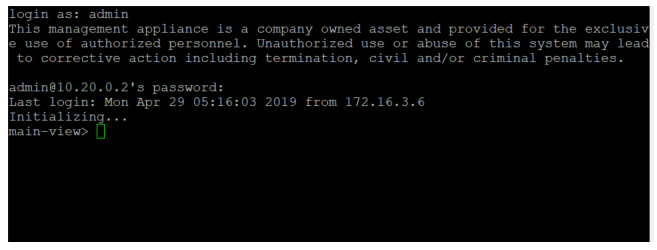
- Navigate to console view.
main-view> console-view console-view> show interconnect list : Enclosure Bay Console Indices Model Serial Number --------- --- --------------- --------------------------------------------- ------------- Frame-01 1 [none] Synergy 10Gb Pass-Thru Module 7C9717001M Frame-01 2 1 Mellanox SH2200 TAA Switch Module for Synergy IL272303CD Frame-01 3 1 Virtual Connect SE 40Gb F8 Module for Synergy 2TV7210064 Frame-01 4 [empty] Frame-01 5 1 Mellanox SH2200 TAA Switch Module for Synergy IL2703000L Frame-01 6 [none] Synergy 20Gb Interconnect Link Module 7C984700FP Frame-02 1 [empty] Frame-02 2 1 Mellanox SH2200 TAA Switch Module for Synergy IL27060022 Frame-02 3 [none] Synergy 20Gb Interconnect Link Module 7C984700DB Frame-02 4 [empty] Frame-02 5 1 Mellanox SH2200 TAA Switch Module for Synergy IL270701TJ Frame-02 6 1 Virtual Connect SE 40Gb F8 Module for Synergy 2TV703006Z - Connect to Bay 2 to erase factory default and erase configuration.
console-view> connect interconnect Frame-02  2
Connecting to interconnect...
To return to the CLI, enter <Ctrl>_. (Control + Shift + Underscore followed
by a period (.) which must be at the beginning of a line)

Frame2-Mellanoxswitchbay2 [standalone: master] >
<Ctrl+C>
Frame2-Mellanoxswitchbay2 [standalone: master] > ena
Frame2-Mellanoxswitchbay2 [standalone: master] # configure t
Frame2-Mellanoxswitchbay2 [standalone: master] (config) # reset factory
Warning - confirming will cause system reboot.

Type 'YES' to confirm reset: yes
- Log in to the OneView IP using SSH.
-
After reboot, follow the onscreen instructions to set up new IP to management Interface.
Mellanox MLNX-OS Switch Management switch-a0aabc login: admin Password: Mellanox Switch Mellanox configuration wizard Do you want to use the wizard for initial configuration? YES Step 1: Hostname? [switch-a0aabc] Frame2-Mellanoxswitchbay5 Step 2: Use DHCP on mgmt0 interface? [yes] no Step 3: Use zeroconf on mgmt0 interface? [no] no Step 4: Primary IPv4 address and masklen? [0.0.0.0/0] 10.20.0.182/24 Step 5: Default gateway? 10.20.0.1 Step 6: Primary DNS server? Step 7: Domain name? Step 8: Enable IPv6? [yes] no Step 9: Admin password (Enter to leave unchanged)? Step 9: Confirm admin password? You have entered the following information: 1. Hostname: Frame2-Mellanoxswitchbay5 2. Use DHCP on mgmt0 interface: no 3. Use zeroconf on mgmt0 interface: no 4. Primary IPv4 address and masklen: 10.20.0.182/24 5. Default gateway: 10.20.0.1 6. Primary DNS server: 7. Domain name: 8. Enable IPv6: no 9. Admin password (Enter to leave unchanged): (CHANGED) To change an answer, enter the step number to return to. Otherwise hit <enter> to save changes and exit. Choice: Configuration changes saved. -
Configure Mellanox MLAG:
- Enable LACP. This is required for the IPL.
- Disable spanning tree (STP). When using MLAG on the switch, there are no loopbacks. Either disable STP globally on the switch or use spanning tree on other interfaces in the switch and disable it on the MLAG interfaces. In most cases, STP is not needed when MLAG is configured.
- Enable IP routing.
- Enable MLAG protocol.
- Enable QoS globally.
Run the following commands on both switches:
sx01 (config) # lacp /* Turn off spanning tree using this command only if using MLNX-OS/Onyx earlier than v3.6.6102: sx01 (config) # no spanning-tree */ sx01 (config) # ip routing sx01 (config) # protocol mlag sx01 (config) # dcb priority-flow-control enable force -
Configure IPL.
IPL is configured over LAG (port-channel). For high availability, it is recommended to have more than one physical link within this LAG. The IPL MTU default configuration is Jumbo Frames (9126) is nonconfigurable. All VLANs are open on this port. There is no need to configure that, as once an interface is mapped as IPL, all the VLANs are open on this port.
In this example, ports 1/21 and 1/22 are used for the IPL connectivity between the switches. The control traffic for the MLAG is sent over the IPL through an L3 interface (interface VLAN).
It is recommended to use a VLAN ID that is not used within the subnet (4093 in this example) to avoid mixing the host traffic with the control traffic on this interface.
NOTE:The IPL link may pass traffic upon MLAG port failures, but not under normal circumstances (when all ports are in UP state).
Run the following commands on both switches:
Configure IP address for the IPL link on both switches.sx01 (config) # interface port-channel 1 sx01 (config interface port-channel 1 ) # exit sx01 (config) # interface ethernet 1/21 channel-group 1 mode active sx01 (config) # interface ethernet 1/22 channel-group 1 mode active sx01 (config) # vlan 4093 sx01 (config vlan 4093) # exit sx01 (config) # interface vlan 4093 sx01 (config interface vlan 4093 ) # exit sx01 (config) # interface port-channel 1 ipl 1 sx01 (config) # interface port-channel 1 dcb priority-flow-control mode on forceNOTE:The IPL IP address should not be part of the management network; it could be any IP address and subnet that is not in use in the network. This address is not advertised outside the switch.
Configure the following on one switch (for example, sx01):sx01 (config) # interface vlan 4093 sx01 (config interface vlan 4093) # ip address 192.168.101.1 255.255.255.0 sx01 (config interface vlan 4093) # ipl 1 peer-address 192.168.101.2Configure the following on the second switch (for example, sx02):sx02 (config) # interface vlan 4093 sx02 (config interface vlan 4093) # ip address 192.168.101.2 255.255.255.0 sx02 (config interface vlan 4093) # ipl 1 peer-address 192.168.101.1 -
Configure MLAG VIP.
MLAG VIP (Virtual IP) is important for retrieving peer information.
NOTE:The IP address should be within the subnet of the management interface (mgmt0).
The management network is used for keep-alive messages between the switches. The MLAG domain must be a unique name for each MLAG domain. If there is more than one pair of MLAG switches on the same network, each domain (consist of two switches) must be configured with a different name. Configure the following on both switches for Frame 1 and Frame 2 with unique mlag-vip names for both frames.
For Frame1:sx01 (config)# mlag-vip my-mlag-vip-frame1 ip 192.168.101.254 /24 forceFor Frame 2:sx01 (config)# mlag-vip my-mlag-vip-frame2 ip 192.168.102.254 /24 forceEnable MLAG globally:switch config) # no mlag shutdown -
MLAG Interface for Uplink and Host.
MLAG configuration is similar to port-channel configuration. It is recommended to keep the same port in each switch within the same MLAG-port-channel (not a must). In this example, there are two MLAG ports, one for each host (host s1 is connected to mlag-port-channel 10 on eth 1/9 and uplink eth1/1 is connected to mlag-port-channel 100).
NOTE:: The mlag-port-channel number is globally significant and must be the same on both switches.
- Configure the following on both switches for dpdk deployment:
sx01 (config) # interface mlag-port-channel 10 sx01 (config interface port-channel 10 ) # exit - To set the MLAG interface in
LACP mode, run on both switches:
sx01 (config) # interface ethernet 1/9 mlag-channel-group 10 mode active - Enable interfaces on both switches:
sx01 (config) # interface mlag-port-channel 10 no shutdown - To change any MLAG port parameter, for example, the MTU, simply enter to the MLAG interface configuration mode and perform the change.
NOTE:
For some operations, use "force" or disable the link manually.
sx01 (config) # interface mlag-port-channel 10
sx01 (config interface mlag-port-channel 10 ) # mtu 9216 force
To change the LAG/MLAG port speed, all interfaces should be removed out of the LAG/MLAG while changing the speed in the member interface configuration mode. It is suggested to do so before adding the ports as members to the LAG/MLAG port as once the ports are members in a LAG/MLAG, there is no option to change the speed, without removing the port from the LAG/MLAG.
- Configure the following on both switches for dpdk deployment:
-
MLAG for Uplink to TOR 5950:
- Configure the following on both switches:
Set the mode (LACP or static). Only one option is applicable.sx01 (config) # interface mlag-port-channel 100 sx01 (config interface port-channel 100 ) # exit - To set the MLAG interface in LACP mode, run:
sx01 (config) # interface ethernet 1/1-1/6 mlag-channel-group 100 mode active - Enable the interfaces:
sx01 (config) # interface mlag-port-channel 100 no shutdownTo change the LAG/MLAG port speed, all interfaces should be removed out of the LAG/MLAG while changing the speed in the member interface configuration mode. It is suggested to do so before adding the ports as members to the LAG/MLAG port as once the ports are members in a LAG/MLAG. There is no option to change the speed, without removing the port from the LAG/MLAG.
- Configure the following on both switches:
-
Configure VLAN on both switches:
sx01 (config) # vlan 2050-2099Allowed vlan on the configured interface port:interface mlag-port-channel 10 switchport mode trunk interface mlag-port-channel 10 switchport trunk allowed-vlan add 2050-2099 interface mlag-port-channel 100 switchport mode trunk interface mlag-port-channel 100 switchport trunk allowed-vlan add 2050-2099 -
Trunk configuration for HOST for SRIOV deployment:
interface ethernet 1/10 switchport mode trunk
interface ethernet 1/10 switchport trunk allowed-vlan add 2050-2099