ACL logging enables the switch to generate a message when IP traffic meets the criteria for a match with an ACE that results in an explicit “deny” or “permit” action. You can use ACL logging to help:
-
Test your network to ensure that your ACL configuration is detecting and denying or “permitting” the IPv4 traffic you do not want forwarded.
-
Receive notification when the switch detects attempts to forward IPv4 traffic you have designed your ACLs to reject (deny) or allow (permit).
The switch sends ACL messages to and optionally to the current console, Telnet, or SSH session. You can use logging < > to configure up to six server destinations.
These requirements are described in more detail in Enabling ACL logging on the switch.
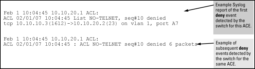
When the switch detects a packet match with an ACE and the ACE includes either the deny or permit action and the optional log parameter, an ACL log message is sent to the designated debug destination.
The first time a packet matches an ACE with deny or permit and log configured, the message is sent immediately to the destination and the switch starts a wait-period of approximately five minutes. (The exact duration of the period depends on how the packets are internally routed.) At the end of the collection period, the switch sends a single-line summary of any additional “deny” or “permit” matches for that ACE (and any other “deny” or “permit” ACEs for which the switch detected a match).
If no further log messages are generated in the wait-period, the switch suspends the timer and resets itself to send a message as soon as a new “deny” or “permit” match occurs. If subsequent packets matching the already logged ACL entries are detected, then a new logged event will be generated that summarizes the number of packets that matched each specific entry (with the time period). The data in the message includes the information illustrated in Content of a message generated by an ACL-deny action.
-
If you are using a server, use the
logging <command to configure the server IPv4 address. Ensure that the switch can access any server you specify.ip-addr> -
Use the
debug destinationcommand to configure one or more log destinations. Destination options includeloggingandsession. For more information on debug, see the “Troubleshooting” section of the Management and Configuration Guide for your switch. -
Use
debug aclordebug allto configure the debug operation to include ACL messages. -
Configure one or more ACLs with the
denyorpermitaction and thelogoption.
By default, the wait period for logging "deny" or "permit" matches (described in ACL logging operation) is approximately five minutes (300 seconds). You can manually set the wait period timer to an interval between 30 and 300 seconds, using the access-list command from the config context. This setting is stored in the switch configuration.
Syntax:
access-list logtimer <default<30-300>>This command sets the wait period timer for logging "deny" or “permit“ messages to the SYSLOG server or other destination device. The first time a packet matches an ACE with deny and
logconfigured, the message is sent immediately to the destination and the switch starts a wait period of approximately five minutes (default value). The exact duration of the period depends on how the packets are internally routed. At the end of the wait period, the switch sends a single-line summary of any additional “deny“ or “permit” matches for that ACE, and any other “deny“ or “permit” ACEs for which the switch detected a match. If no further log messages are generated in the wait period, the switch suspends the timer and resets itself to send a message as soon as a new “deny“ or “permit” match occurs.
ACL statistics counters provide a means for monitoring ACL performance by using counters to display the current number of matches the switch has detected for each ACE in an ACL assigned to a switch interface. This can help in determining whether a particular traffic type is being filtered by the intended ACE in an assigned list, or if traffic from a particular device or network is being filtered as intended.
Syntax:
Displays the current match (hit) count per ACE for the specified IPv6 or IPv4 static ACL assignment on a specific interface.
show: Displays the current match (hit) count per ACE for the specified IPv6 or IPv4 static ACL assignment on a specific interface.
clear: Resets ACE hit counters to zero for the specified IPv6 or IPv4 static ACL assignment on a specific interface.
Total: This column lists the running total of the matches the switch has detected for the ACEs in an applied ACL since the ACL’s counters were last reset to 0 (zero).
IPv6 and IPv4 ACL statistics
HP Switch# show statistics aclv6 IPV6-ACL vlan 20 vlan

 HitCounts for ACL IPV6-ACL

  Total
(   12)  10 permit icmp ::/0 fe80::20:2/128
(    6)  20 deny tcp ::/0 fe80::20:2/128 eq 23 log
(   41)  30 permit ipv6 ::/0 ::/0

HP Switch# show statistics aclv4 102 vlan 20 vlan

 HitCounts for ACL 102

  Total
(   4)  10 permit icmp 10.10.20.3 0.0.0.0 10.10.20.2 0.0.0.0 8
(   8)  20 deny icmp 0.0.0.0 255.255.255.255 10.10.20.2 0.0.0.0 8
(   2)  30 permit tcp 10.10.20.3 0.0.0.255 10.10.20.2 0.0.0.255 eq 23
(   2)  55 deny tcp 0.0.0.0 255.255.255.255 10.10.20.2 0.0.0.0 8
( 125)  60 permit ip 0.0.0.0 255.255.255.255 0.0.0.0 255.255.255.255
ACE counter operation: For a given ACE in an assigned ACL, the counter increments by 1 each time the switch detects a packet that matches the criteria in that ACE, and maintains a running total of the matches since the last counter reset.
|
|
|
![[NOTE: ]](images/note.gif) |
NOTE: This ACL monitoring feature does not include hits on the “implicit deny” that is included at the end of all ACLs. |
|
|
Resetting ACE hit counters to zero:
The following example shows a sample of performance monitoring output for an IPv6 ACL assigned as a VACL.
IPv6 ACL performance monitoring output
HP Switch# show statistics aclv6 V6-02 vlan 20 vlan

 HitCounts for ACL V6-02

  Total
(   5) 10 permit icmp ::/0 fe80::20:2/128
(   4) 20 permit icmp ::/0 fe80::20:3/128
( 136) 30 permit tcp fe80::20:1/128 ::/0 eq 23
(   2) 40 deny icmp ::/0 fe80::20:1/128
(  10) 50 deny tcp ::/0 ::/0 eq 23
(   8) 60 deny icmp ::/0 ::/0
( 155) 70 permit ipv6 ::/0 ::/0
The following example sample of performance monitoring output for an IPv4 ACL assigned as a VACL.
IPv4 ACL performance monitoring output
HP Switch# show statistics aclv4 102 vlan 20 vlan

 HitCounts for ACL 102

  Total
(  1) 10 permit icmp 10.10.20.3 0.0.0.0 10.10.20.2 0.0.0.0 8
(  2) 20 deny icmp 10.10.20.3 0.0.0.0 10.10.20.1 0.0.0.0 8 log
(  2) 30 deny icmp 10.10.20.2 0.0.0.0 10.10.20.3 0.0.0.0 8 log
(  1) 40 deny icmp 10.10.20.2 0.0.0.0 10.10.20.1 0.0.0.0 8 log
( 10) 50 deny tcp 10.10.20.2 0.0.0.255 10.10.20.3 0.0.0.255 eq 23 log
( 27) 60 permit ip 0.0.0.0 255.255.255.255 0.0.0.0 255.255.255.255
The following example uses the counter activity in IPv6 ACL performance monitoring output to demonstrate using clear statistics to reset the counters to zero.
IPv6 ACL performance monitoring output
HP Switch# show statistics aclv6 V6-02 vlan 20 vlan

 HitCounts for ACL V6-02

  Total

(   5) 10 permit icmp ::/0 fe80::20:2/128 128
(   4) 20 permit icmp ::/0 fe80::20:3/128 128
( 136) 30 permit tcp fe80::20:1/128 ::/0 eq 23
(   2) 40 deny icmp ::/0 fe80::20:1/128 128
(  10) 50 deny tcp ::/0 ::/0 eq 23
(   8) 60 deny icmp ::/0 ::/0 133
( 155) 70 permit ipv6 ::/0 ::/0

HP Switch# clear statistics aclv6 V6-02 vlan 20 vlan
HP Switch# show statistics aclv6 V6-02 vlan 20 vlan

 HitCounts for ACL V6-02

  Total

(   0) 10 permit icmp ::/0 fe80::20:2/128 128
(   0) 20 permit icmp ::/0 fe80::20:3/128 128
(   0) 30 permit tcp fe80::20:1/128 ::/0 eq 23
(   0) 40 deny icmp ::/0 fe80::20:1/128 128
(   0) 50 deny tcp ::/0 ::/0 eq 23
(   0) 60 deny icmp ::/0 ::/0 133
(   0) 70 permit ipv6 ::/0 ::/0
|
|
|
|
|
NOTE: The examples of counters in this section use small values to help illustrate counter operation. The counters in real-time network applications are generally much more active and show higher values. |
|
|
Where the same IPv6 ACL is assigned to multiple interfaces, the switch maintains a separate instance of each ACE counter in the ACL. When there is a match with traffic on one of the ACL’s assigned interfaces, only the affected ACE counters for that interface are incremented. Other instances of the same ACL applied to other interfaces are not affected.
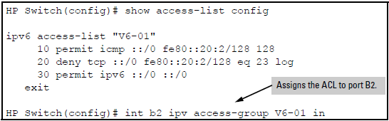
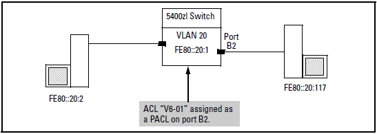
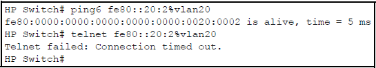
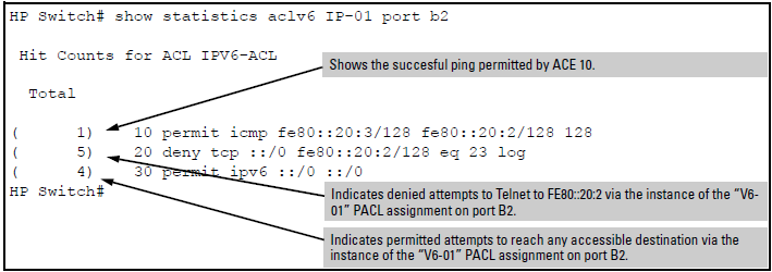
Using the topology in figure 8-39, a workstation at FE80::20:117 on port B2 attempting to ping and Telnet to the workstation at FE80::20:2 is filtered through the PACL instance of the “V6-01” ACL assigned to port B2, resulting in the following: