The HP 640 Redundant/External Power Supply Shelf (J9805A) is an external shelf that can house up to three power supplies (PSUs). The PSUs installed in the HP 640 RPS/EPS Shelf can supply redundant power to HP 2920 PoE and non-PoE Switches in the event of an HP 2920 Switch internal power supply failure, and can provide additional PoE power to the 2920 PoE Switches. This section discusses the switch CLI external-power-supply command options used to configure the HP 2920 Switches for operation with the HP 640 RPS/EPS. The HP 640 RPS/EPS Shelf is also identified as the XPS, since that is how it is identified in the HP 2920 Switch software.
For complete information on the HP 640 RPS/EPS Shelf installation, physical setup options, and troubleshooting, see the HP 640 RPS/EPS Shelf Installation and Power Setup Guide online at www.hp.com/networking. Auto search on “640”, select the device in the list, and click onDisplay selected. Then click on the links that have “manuals” in them to get to the web page that lists the available manuals.
The same PSUs can be used in both the HP 2920 Switches and the XPS. Each XPS zone can hold any of the supported PSUs. The supported PSUs are these:
-
HP X332 1050W PSU (J9737A) is a 54V power supply unit that can provide 740W of PoE power and a maximum power rating of 1050W (combined system and PoE power).
-
HP X332 575W PSU (J9738A) is a 54V power supply unit that can provide 370W of PoE power and a maximum power rating of 575W (combined system and PoE power).
-
HP X3312 165W PSU (J9739) is a 12V power supply unit providing non-PoE power. It is not accepted in PoE switches.
HP 640 RPS/EPS with supported power supplies shows an Example: of the three PSUs installed in the XPS zones and the power that they provide.
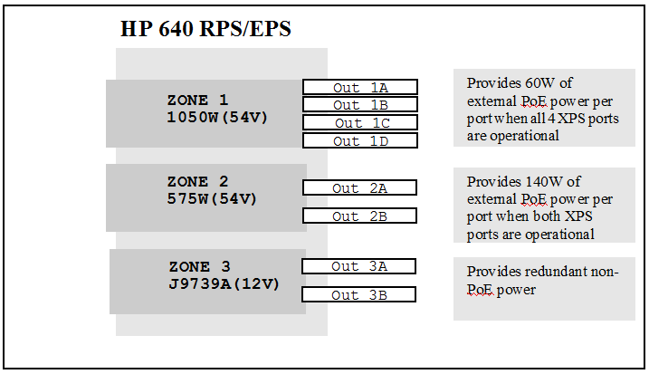
In addition to the voltage and power differences between the three PSUs, the non-PoE J9739A PSU has a mechanical key that is different from the PoE PSUs. The mechanical key prevents the insertion of a PoE PSU into a non-PoE switch, or a non-PoE PSU into a PoE switch. This keying function is not needed for the HP 640 RPS/EPS as it can accept all three types of PSUs—PoE and non-PoE.
The XPS can be used to provide PoE power to an HP 2920-PoE switch in addition to the power from the switch’s internal power supply (IPS). The amount of available external power depends on which external power supplies are installed in the XPS and how the power zones have been configured.
The information in tables below shows the maximum amount of PoE power that is available for various power supply configurations. It is important to use the information displayed in these tables when determining the power supplied for a configuration, as they accurately represent the maximum power that is available.
Maximum PoE power available with 575W PSU in 640 RPS/EPS
| Number of ports enabled in the zone | For 2920 Switch with 575W PSU and 640 RPS/EPS with 575W PSU | For 2920 Switch with 1050W PSU and 640 RPS/EPS with 575W PSU | |||||
|---|---|---|---|---|---|---|---|
| PoE from 640 RPS/EPS PSU | PoE from switch PSU | Total PoE | PoE from 640 RPS/EPS PSU | PoE from switch PSU | Total PoE | ||
|
1 port (zones 1,2, or 3) |
370W |
370W |
740W |
0W (not supported) The PSU in the 640 RPS/EPS must have equal to or greater power (Watts) than the PSU in the switch. |
740W |
740W |
|
|
2 ports (zones 1, 2, or 3) |
140W |
370W |
510W |
740W |
740W |
||
|
3 ports (zone 1 only) |
60W |
370W |
430W |
740W |
740W |
||
|
4 ports (zone 1 only) |
0W |
370W |
370W |
740W |
740W |
||
Maximum PoE power available with 1050W PSU in 640 RPS/EPS
| Number of ports enabled in the zone | For 2920 Switch with 575W PSU and 640 RPS/EPS with 1050W PSU | For 2920 Switch with 1050W PSU and 640 RPS/EPS with 1050W PSU | |||||
|---|---|---|---|---|---|---|---|
| PoE from 640 RPS/EPS PSU | PoE from switch PSU | Total PoE | PoE from 640 RPS/EPS PSU | PoE from switch PSU | Total PoE | ||
|
1 port (zones 1,2, or 3) |
700W |
370W |
1070W |
700W |
740W |
1440W |
|
|
2 ports (zones 1, 2, or 3) |
370W |
370W |
740W |
370W |
740W |
1110W |
|
|
3 ports (zone 1 only) |
130W |
370W |
500W |
130W |
740W |
870W |
|
|
4 ports (zone 1 only) |
60W |
370W |
430W |
60W |
740W |
800W |
|
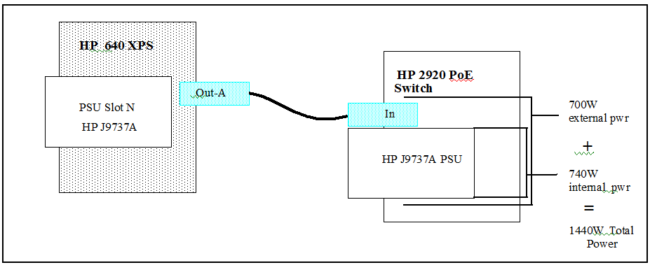
For example, the internal 1050W PSU can supply 740 watts of internal PoE power to the PoE ports. With the addition of an XPS containing a 1050W PSU, an additional 700 watts of external PoE power can be delivered to the PoE ports, for a total of 1440W of PoE power. This is the maximum amount of PoE power that can be supplied to the switch ports (30W per port x 48 ports = 1440W).
As shown in Maximum PoE power available with 575W PSU in 640 RPS/EPS, though, when a 575W PSU is installed in Zone 1 and all four ports are enabled, there is redundancy protection, but zero watts of external PoE power from the XPS.
The following table illustrates three basic setups for HP 2920 Switches and using an HP 640 RPS/EPS for extra PoE power.
Example: basic setups for switches using the XPS
| Power | Total power Available per switch | # of Switches/Zone | Switch PSU Model | RPS/EPS PSU Model | Description |
|---|---|---|---|---|---|
|
1440W |
1440W30W for 48 ports |
1 |
1050W |
1050W |
740W internal power and 700W external PoE power |
|
740W, one switch |
30W for 24 ports or 15.4W for 48 ports |
1 |
575W |
575W |
370W internal power and 370W external PoE power |
|
740W, zone with 2 switches |
30W for 24 ports, or 15.4W for 48 ports |
2 |
575W |
1050W |
370W internal power and 370W of external power for each switch |
An external PSU and an internal PSU combined to provide 1440W of total PoE power shows an Example: physical connection between an HP 640 RPS/EPS Shelf with a 1050W PSU installed and an HP 2920 Switch also with a 1050W PSU installed. The resulting PoE Power is indicated.
For complete information about configuration options, see the HP 640 RPS/EPS Shelf Installation and Power Setup Guide online at www.hp.com/networking. Auto search on “640”, select the device in the list, and click onDisplay selected. Then click on the links that have “manuals” in them to get to the web page that lists the available manuals.
There will be power flow between the switch and the XPS if these conditions are met:
-
PSUs in the HP 2920 switch and the HP 640 XPS are valid, recognized models.
-
The zone configuration for all the switches in that zone is supported.
-
The power of the PSU in the XPS must always be equal to or larger than the power of the internal power supply in any switch in the same zone.
A 575W PSU installed in an HP 640 XPS zone cannot be used to provide power to any switch that contains a 1050W PSU. An error message displays and there is no flow of power. You must use a 1050W PSU in the HP 640 XPS to supply the PoE power for that zone.
It is OK to have a 1050W PSU in the XPS and a 575W PSU in the connected switch.
-
Any necessary reduction of external PoE power in any switch is performed in an orderly and configured way before another switch is added.
Using the XPS as a redundant power supply provides N+1 redundancy to the first switch that fails in the zone. For example, if two HP 2920 switches are connected to the same zone and the PSU in the first switch fails, the XPS then provides 12V power to that switch to keep it operating. The 12V power from the XPS to the second switch is disabled, and that switch continues to operate under power from its own IPS, but it no longer has N+1 redundancy.
The XPS continues to provide PoE power to both switches but the total PoE power for both switches is reduced. As a result, some of the PoE devices connected to both switches might lose power, depending on how many devices are connected and how much PoE power they are using.
|
|
|
![[NOTE: ]](images/note.gif) |
NOTE: Only one PSU failure is supported. Multiple failures are not supported. |
|
|
The HP 165W non-PoE PSU (J9739A) is the only power supply used with non-PoE HP 2920 switches. If a J9739A PSU is installed in an XPS zone, then only HP 2920 non-PoE Switches can be connected to that zone. The XPS provides redundant (N+1) power if the power supply in one of the non-PoE switches fails. The power flows to the switch with the failed power supply. For any other switches connected to that zone, the power flow is disabled until the failed PSU is replaced. The switches continue to operate without interruption and continue to communicate with the XPS.
If the HP J9739A power supply that fails is installed in the XPS, all power flow to all switches connected to that zone is disabled until the failed PSU is replaced. The connected switches continue to operate without interruption, but communication with the XPS may stop, depending on the severity of the failure.
For more information about supported configurations and redundant behavior, see the HP 640 RPS/EPS Shelf Installation and Power Setup Guide online at www.hp.com/networking. Auto search on “640”, select the device in the list, and click onDisplay selected. Then click on the links that have “manuals” in them to get to the web page that lists the available manuals.
To configure the HP 2920 PoE Switches to use the PoE power from the XPS, you will issue external-power-supply commands to the switches. By default, all the available PoE power is shared equally by all the switches connected to a given XPS zone. To cause a redistribution of this power, you must issue the external-power-supply commands to all of the switches that are connected to that zone.
|
|
|
|
|
NOTE: Configuring HP 2920 Switches that are Members of a 2920 Stack. If the |
|
|
In the XPS default configuration, the switch automatically receives backup power and external PoE power (for PoE switches that require it) when an HP 2920 Switch is connected to an XPS port. Auto-recovery is also enabled in the default configuration. The following command lets you control whether the switch receives the XPS power, if you need to do so.
Syntax:
Permits power to be supplied or discontinued from the XPS to the switch or to a member of a stack of switches.
enableTurns on the XPS port to provide power to the switch. When the switch is connected to an XPS port, it automatically receives backup power and PoE power.
The XPS is enabled by default with the auto-recovery feature.
NOTE: If the
external-power-supply disablecommand is executed, auto-recovery is disabled and you must execute theexternal-power-supply auto-recovery enablecommand to re-enable auto-recovery. Executing theexternal-power-supply enablecommand does not re-enable auto-recovery.
disableTurns off the XPS port. Auto-recovery on the switch is turned off as well. The disable option can be used to turn off the XPS even if the cable is part of the current distribution map. This can be useful for troubleshooting.
Syntax:
When enabled, the auto-recovery feature allows the switch to configure itself if an internal PSU or an external PSU has a power failure and is replaced. The switch begins to receive backup power.
enableWhen the switch is connected to an XPS port and the port is part of the distribution map, the XPS can provide redundant or external power.
Default: Enabled
disableWhen auto-recovery is disabled, the switch must be reconfigured to obtain backup power in case of a power supply failure or the hotswap of the XPS cable.
Disabling auto-recovery for a specified 2920 stack member
HP Switch(config)# external-power-supply member 1 auto-recovery disable
This will disable the auto recovery feature enabled on this member. External
power supply needs to be re-enabled in case of power supply failure or hot swap
of power supply cable or change in distribution map with ‘force’.
Continue (y/n)? y
Disabling auto-recovery for the switch
HP Switch(config)# external-power-supply auto-recovery disable
This will disable the auto recovery feature enabled on this switch. External
power supply needs to be re-enabled in case of power supply failure or hot swap
of power supply cable or change in distribution map with ‘force’.
Continue (y/n)? y
Syntax:
Restores the XPS configuration on the current zone to factory default settings. This may power down some PoE ports.
Default: All XPS ports are operational.
For a stack of switches, the zone connected to the specified member is reset to its factory default configurations. Specify the member-id to configure the zone to which the member is connected.
NOTE: This command is not available in stacking member context.
Restoring the default external power supply settings
HP Switch(config)# external-power-supply reset

This will reset the external power supply to factory default configurations.
This might shutdown powered PoE ports on the connected switches.

Continue (y/n)? y
Configuring external power supply, this might take up to a minute...
Syntax:
Configures the XPS to distribute power to the ports specified. The amount of XPS power received by each XPS port depends on the number of ports that have been specified.
NOTE: This command is not available in stacking member context.
[force]
When the
forceoption is selected, the zone can be re-configured. This allows an additional switch to be added to the existing setup. External PoE power is distributed to the newly added switch, however, this will result in the temporary shutdown of all PoE devices connected to PoE ports on the affected switches that are receiving their PoE power from the XPS. PoE devices that are receiving their PoE power from the switch’s IPS will continue operation. For more information, see Example: of using the force option.
This Example: is for a configuration with a distribution map of 1A, 1B, 1C, and 1D, but you want power from the XPS to be available to only ports 1A and 1C.
Configuration for power allocation
HP Switch(config)# external-power-supply power-share 1A, 1C

This would change the allocated power for XPS port 1A, 1C to 370W, disable XPS
ports 1B, 1D and change their allocated power to 0W. This might cause PoE power
ports connected in system 1B, 1D to be shut down.

Continue (y/n)? y
Configuring external power supply, this might take up to a minute...
This Example: illustrates adding a new switch to 1D with a current distribution map of 1A, 1C.
Configuring power allocation when adding a switch
HP Switch-1A(config)# external-power-supply power-share allow 3

HP Switch-1C(config)# external-power-supply power-share allow 3

HP Switch(config)# external-power-supply power-share 1A,1C,1D
This would change allocated power for XPS port 1A, 1C, 1D to 130W.
Continue (y/n)? y
Configuring external power supply, this might take up to a minute...
The force option allows you to force an immediate change to the PoE power distribution for a specified XPS zone. The force option can be convenient in that it needs to be issued to only the switch that is being added to the zone. For the “graceful” method of power redistribution, using the external-power-supply allow and external-power-supply < command sequence, you must issue these commands to all of the affected switches in the zone. But, using the force option has consequences in the PoE power delivery to the affected switches. See the important note below.xps ports>
![[IMPORTANT: ]](images/important.gif)
This Example: uses the force option to change the power allocation.
Non-graceful method for adding a switch and distributing external power
HP Switch(config)# external-power-supply power-share 1D force
This would change allocated power for XPS port 1D to 370W,
disable XPS ports 1A, 1B, 1C and change their allocated power to 0W.
This might result in PoE powered ports connected in system 1A, 1B, 1C, 1D to be shutdown.
Continue (y/n)?  y
Configuring external power supply, this might take up to a minute...
Syntax:
Provides a graceful way to reduce the allocated external power when a switch is added to an existing XPS setup.
NOTE: This command is not available in stacking member context.
This command is executed when a new switch is connected to an existing XPS setup. To distribute power to the newly added switch, execute this command on each connected switch to reduce the allocated power so that the new switch can draw power from the XPS. This may cause some PoE devices connected to the switches to be powered down because the total PoE power going to each switch will be reduced.
For example, if a switch is connected to an XPS zone with one other switch, and a third switch is added to that zone (must be Zone 1 which is the only zone with more than two ports), then the following command should also be executed on all the switches connected to this zone.
If the non-PoE switch and the XPS are in their default configurations, run the show external-power-supply briefcommand to verify that there is adequate XPS power to provide redundancy power to the switch.
If the non-PoE switch has auto-recovery disabled and the XPS is not providing redundancy support to the switch, execute the commands as shown in Enabling an XPS for a non-PoE switch configuration.
Enabling an XPS for a non-PoE switch configuration
HP Switch(config)# external-power-supply enable

HP Switch(config)# show external-power-supply brief
External Power Supply Type          : HP 640 Redundant/External PS Shelf
External Power Supply Serial Number : CN36FX201L
External Power Supply Module        : J9805A
External Power Supply PSU Revision  : 0
External Power Supply PSU Module    : J9739A
Voltage / Wattage                   : 12V / 165W
Current Zone                        : 2
Zone State                          : Powered
Zone Record Version                 : 3

Cable Port  Connection    XPS     Mbr System Name
Id    Allow Status        Enabled Id
----- ----- ------------ ------- --- -----------
2A*   Yes   Available     Yes     -   HP-2920-24G
2B    Yes   Not Connected
If you want to enable auto-recovery as well, execute the external-power-supply auto-recovery enable command.
Enabling an XPS and auto-recovery for a non-PoE switch configuration
HP Switch(config)# external-power-supply auto-recovery enable

HP Switch(config)# show external-power-supply detail

External Power Supply Type          : HP 640 Redundant/External PS Shelf
External Power Supply Serial Number : CN36FX201L
External Power Supply Module        : J9805A
External Power Supply PSU Revision  : 0
External Power Supply PSU Module    : J9739A
Voltage / Wattage                   : 12V / 165W
Current Zone                        : 1
Zone State                          : Powered
Zone Record Version                 : 3

Cable ID : 1A

  System Name                  : HP 2920-24G-PoE+ Switch
  Stack Id                     : 00010021-f73bdd81
  Member Id                    : 1
  Module                       : J9727A
  MAC Address                  : 0021f7-78d6d0
  Software Version             : WB.15.13.0000x
  Serial Number                : SG2ZFLX098
  Internal Power Supply Rating : 12V / 165W
  External Power               : 0 W
  Connection Status            : Available
  Auto Recovery                : Yes
  Cable Record Version         : 3
  Supported Zone Record Version: 3
Distribution of PoE power shows the configuration for an HP 2920 switch with a 1050W IPS, and an XPS with a 1050W PSU. Execute the show external-power-supply brief command to view the current status of the power distribution. The output shows that the XPS is providing 60W of external PoE power to each XPS port and the port’s connected switch.
Distribution of PoE power
HP Switch(config)# show external-power-supply brief

External Power Supply Type          : HP 640 Redundant/External PS Shelf
External Power Supply Serial Number : CN36FX201L
External Power Supply Module        : J9805A
External Power Supply PSU Revision  : 0
External Power Supply PSU Module    : J9737A
Voltage / Wattage                   : 54V / 1050W
Current Zone                        : 1
Zone State                          : Powered
Zone Record Version                 : 3

Cable Port  Connection    XPS     Ext.    Mbr System Name
Id    Allow Status        Enabled Power   Id
----- ----- ------------  ------- ------- --- -----------
1A*   Yes   Available     Yes     60  W   -   HP-2920-48G-POE+
1B    Yes   Available     Yes     60  W   -   HP-2920-48G-POE+
1C    Yes   Available     Yes     60  W   -   HP-2920-24G-PoEP
1D    Yes   Available     Yes     60  W   -   HP-2920-24G-PoEP
As shown in Distribution of PoE power after redistribution, executing the power-share command to cause all power to be distributed to port 1A changes the allocated power 700W for that port. XPS ports 1B, 1C, and 1D are disabled and the allocated power for each is now zero watts.
Distribution of PoE power after redistribution
HP Switch(config)# external-power-supply power-share 1A
This would change allocated power for XPS port 1A to 700W,
disable XPS ports 1B, 1C, 1D and change their allocated power to 0W.
This might result PoE powered ports connected in system 1B, 1C, 1D to
be shutdown.
Continue (y/n)?  y
Configuring external power supply, this might take up to a minute...


HP Switch(config)# show external-power-supply brief

External Power Supply Type          : HP 640 Redundant/External PS Shelf
External Power Supply Serial Number : CN36FX201L
External Power Supply Module        : J9805A
External Power Supply PSU Revision  : 0
External Power Supply PSU Module    : J9737A
Voltage / Wattage                   : 54V / 1050W
Current Zone                        : 1
Zone State                          : Powered
Zone Record Version                 : 3

Cable Port  Connection    XPS     Ext.    Mbr System Name
Id    Allow Status        Enabled Power   Id
----- ----- ------------  ------- ------- --- -----------
1A*   Yes   Available     Yes     700 W   -   HP-2920-48G-POE+
1B    No    Unavailable   No      0   W   -   HP-2920-48G-POE+
1C    No    Unavailable   No      0   W   -   HP-2920-24G-PoEP
1D    No    Unavailable   No      0   W   -   HP-2920-24G-PoEP
Output displaying PoE power available
HP Switch(config)# show power-over-ethernet

 Status and Counters - System Power Status

  System Power Status    : Full redundancy
  PoE Power Status       : No redundancy

 Chassis power-over-ethernet:

  Total Available Power  : 1440 W
  Total Failover Power   :  740 W
  Total Redundancy Power :    0 W
  Total Used Power       :    0 W +/- 6W
  Total Remaining Power  : 1440 W

 Internal Power
        1   740W/POE+ /Connected.
 External Power
        EPS1   700W /Connected.
Before configuring external PoE power for multiple HP 2920 switches, execute the show external-power-supply brief command to determine the current XPS configuration. XPS PoE power delivered to a single switch shows an XPS with a 1050W PSU (J9737A) in zone 1 connected to four HP 2920 switches. Assume, for this Example: that each of the switches also contains a 1050W (J9737A) IPS. The figure shows a current configuration with 700W of PoE power being delivered only to XPS port 1A.
XPS PoE power delivered to a single switch
HP Switch(config)# show external-power-supply brief

External Power Supply Type          : HP 640 Redundant/External PS Shelf
External Power Supply Serial Number : CN36FX201L
External Power Supply Module        : J9805A
External Power Supply PSU Revision  : 0
External Power Supply PSU Module    : J9737A
Voltage / Wattage                   : 54V / 1050W
Current Zone                        : 1
Zone State                          : Powered
Zone Record Version                 : 3

Cable Port  Connection    XPS     Ext.    Mbr System Name
Id    Allow Status        Enabled Power   Id
----- ----- ------------  ------- ------- --- -----------
1A*   Yes   Available     Yes     700 W   -   HP-2920-48G-POE+
1B    No    Unavailable   No      0   W   -   HP-2920-48G-POE+
1C    No    Unavailable   No      0   W   -   HP-2920-24G-PoEP
1D    No    Unavailable   No      0   W   -   HP-2920-24G-PoEP
To change the power distribution to deliver power to all four XPS ports and their connected switches, execute the external-power-supply power-share commands as shown in Distributing XPS PoE power to multiple switches. Note that the allow 4 command must be executed on all three of the switches that are currently sharing the power – the switches connected to ports 1A, 1B, and 1C. Then, the command to specify the new distribution map is executed on the switch that is being added – the switch connected to port 1D.
After executing those commands, the show external-power-supply brief command now displays 60W of PoE power being delivered to all four XPS ports and their connected switches.
Distributing XPS PoE power to multiple switches
HP Switch-1A(config)# external-power-supply power-share allow 4

HP Switch-1B(config)# external-power-supply power-share allow 4

HP Switch-1C(config)# external-power-supply power-share allow 4

HP Switch-1D(config)# external-power-supply power-share 1A,1B,1C,1D
This would change allocated power for XPS port 1A,1B,1C,1D to 60W.
Continue (y/n) y
Configuring external power supply, this might take up to a minute...

HP Switch(config)# show external-power-supply brief

External Power Supply Type          : HP 640 Redundant/External PS Shelf
External Power Supply Serial Number : CN36FX201L
External Power Supply Module        : J9805A
External Power Supply PSU Revision  : 0
External Power Supply PSU Module    : J9737A
Voltage / Wattage                   : 54V / 1050W
Current Zone                        : 1
Zone State                          : Powered
Zone Record Version                 : 3

Cable Port  Connection    XPS     Ext.    Mbr System Name
Id    Allow Status        Enabled Power   Id
----- ----- ------------  ------- ------- --- -----------
1A*   Yes   Available     Yes     60  W   -   HP-2920-48G-POE+
1B    Yes   Available     Yes     60  W   -   HP-2920-48G-POE+
1C    Yes   Available     Yes     60  W   -   HP-2920-24G-PoEP
1D    Yes   Available     Yes     60  W   -   HP-2920-24G-PoEP
|
|
|
|
|
NOTE: As shown in Distributing XPS PoE power to multiple switches using the force option, the same results could be accomplished by using a single command issued to the switch connected to port 1D, and by using the force option. As noted in the message provided by the switch software though, PoE power that is being provided to any of the XPS ports might be temporarily shut down while the new power distribution is activated. Port 1A was the only port receiving power, so it is the only one listed: This might result in PoE powered ports connected in system 1A to be shutdown. |
|
|
Distributing XPS PoE power to multiple switches using the force option
HP Switch(config)# external-power-supply power-share 1A,1B,1C,1D force
This would change allocated power for XPS port 1A,1B,1C,1D to 60W.
This might result in PoE powered ports connected in system 1A to be shutdown.
Continue (y/n) y
For more information, see Example: of using the force option.
Syntax:
Displays information about the XPS operational and configuration parameters.
If the switch is a member of a stack of switches, the member-id must be specified to obtain information about the zone to which the member is connected. In the output, an asterisk ( “*”) next to the cable ID denotes the current member from which the command is executed.
NOTE: This command is not available in stacking member context.
briefDisplays brief information about the XPS operational and configuration parameters.
detailDisplays detailed information about the XPS operational and configuration parameters.
infoDisplays the power received per switch based on the number of switches connected to the zone.
XPS parameter information includes:
External Power Supply PSU Revision: The current revision of the PSU.
Voltage/Wattage: The total voltage and wattage available with that PSU.
Zone Record Version: The current version of the zone record.
Connection Status: The connection is available, unavailable, not connected, or mismatched. Mismatched connections occur when the PSU is not supported in that configuration.
XPS Enabled: The XPS port is enabled or disabled for power delivery.
Ext. Power: The amount of external power that is allocated, in watts.
The amount of power received by a port is determined by the distribution map and the type of power supplies used.
Output when 3 PoE switches are connected to an EPS/RPS 640 power supply
HP Switch(config)# show external-power-supply member 1 brief


External Power Supply Type          : HP 640 Redundant/External PS Shelf
External Power Supply Serial Number : CN36FX202L
External Power Supply Module        : J9805A
External Power Supply PSU Revision  : 1
External Power Supply PSU Module    : J9738A
Voltage / Wattage                   : 54V / 575W
Current Zone                        : 1
Zone State                          : Powered
Zone Record Version                 : 3


Cable Port  Connection    XPS     Ext.    Mbr System Name
Id    Allow Status        Enabled Power   Id
----- ----- ------------  ------- ------- --- ----------
1A*   Yes   Available     Yes     0 W     1   2-mbr-stack
1B    Yes   Available     Yes     0 W     2   2-mbr-stack
1C    Yes   Not Connected
1D    Yes   Available     Yes     0 W     -   HP-2920-48G-POE+
The asterisk beside the cable ID, For example, 1A*, indicates the switch that is communicating with the XPS for information. Output when 3 PoE switches are connected to an EPS/RPS 640 power supply indicates that the switch connected to XPS port 1A is communicating with the XPS. For a stack of switches, all XPS ports in the same stack will display the asterisk beside the cable ID.
Output for a 4-member stack of switches when no member is specified
HP Switch(config)# show external-power-supply brief

External power supply information for members 1,2,3,4

External Power Supply Type          : HP 640 Redundant/External PS Shelf
External Power Supply Serial Number : CN2ZFX2027
External Power Supply Module        : J9805A
External Power Supply PSU Revision  : 0
External Power Supply PSU Module    : J9737A
Voltage / Wattage                   : 54V / 1050W
Current Zone                        : 1
Zone State                          : Powered
Zone Record Version                 : 3

Cable Port  Connection    XPS     Ext.    Mbr System Name
Id    Allow Status        Enabled Power   Id
----- ----- ------------  ------- ------- --- -----------
1A*   Yes   Available     Yes     60  W   4   HP-Stack-2920
1B*   Yes   Available     Yes     60  W   3   HP-Stack-2920
1C*   Yes   Available     Yes     60  W   2   HP-Stack-2920
1D*   Yes   Available     Yes     60  W   1   HP-Stack-2920
The output varies depending on the switch from which the command is executed. An asterisk next to the port ID indicates where the command was executed. In Output when command is executed from PoE switch 1C connected to a PoE zone the command is executed from a non-Stack PoE switch connected to XPS port 1C in a PoE zone. In Output when command is executed from non-PoE switch 1B connected to a PoE zone the command is executed from a non-PoE switch connected to XPS port 1B in a PoE zone.
Output when command is executed from PoE switch 1C connected to a PoE zone
HP Switch(config)# show external-power-supply brief

External Power Supply Type          : HP 640 Redundant/External PS Shelf
External Power Supply Serial Number : CN36FX201L
External Power Supply Module        : J9805A
External Power Supply PSU Revision  : 0
External Power Supply PSU Module    : J9737A
Voltage / Wattage                   : 54V / 1050W
Current Zone                        : 1
Zone State                          : Powered
Zone Record Version                 : 3

Cable Port  Connection    XPS     Ext.    Mbr System Name
Id    Allow Status        Enabled Power   Id
----- ----- ------------  ------- ------- --- -----------
1A    Yes   Available     Yes     60  W   -   HP-2920-48G-POE+
1B    Yes   Unavailable   No      0   W   -   HP-2920-24G
1C*   Yes   Available     Yes     60  W   -   HP-2920-24G-PoEP
1D    Yes   Available     Yes     60  W   -   HP-2920-24G-PoEP
Output when command is executed from non-PoE switch 1B connected to a PoE zone
HP Switch(config)# show external-power-supply brief

External Power Supply Type          : HP 640 Redundant/External PS Shelf
External Power Supply Serial Number : CN36FX201L
External Power Supply Module        : J9805A
External Power Supply PSU Revision  : 0
External Power Supply PSU Module    : J9737A
Voltage / Wattage                   : 54V / 1050W
Current Zone                        : 1
Zone State                          : Powered
Zone Record Version                 : 3

Cable Port  Connection    XPS     Ext.    Mbr System Name
Id    Allow Status        Enabled Power   Id
----- ----- ------------  ------- ------- --- -----------
1A    Yes   Available     Yes     60  W   -   HP-2920-48G-POE+
1B*   Yes   Mismatch      No      0   W   -   HP-2920-24G
1C    Yes   Available     Yes     60  W   -   HP-2920-24G-PoEP
1D    Yes   Available     Yes     60  W   -   HP-2920-24G-PoEP
Output for info option with the 575W PSU (J9738A) installed in zone 1
HP Switch(config)# show external-power-supply info

External Power Supply Type          : HP 640 Redundant/External PS Shelf
External Power Supply Serial Number : CN36FX202L
External Power Supply Module        : J9805A
External Power Supply PSU Revision  : 1
External Power Supply PSU Module    : J9738A
Voltage / Wattage                   : 54V / 575W
Current Zone                          : 1
Zone State                          : Powered
Zone Record Version                 : 3

Number of Switches   Power Received
Connected            Per Switch
------------------   -----------------
1                    370 W
2                    140 W
3                    60  W
4                    0   W
Truncated output for detail option with a 575W PSU (J9738A) installed in zone 1 with 3 HP 2920 Switches configured
HP Switch(config)# show external-power-supply detail

External Power Supply Type          : HP 640 Redundant/External PS Shelf
External Power Supply Serial Number : CN36FX202L
External Power Supply Module        : J9805A
External Power Supply PSU Revision  : 1
External Power Supply PSU Module    : J9738A
Voltage / Wattage                   : 54V / 575W
Current Zone                        : 1
Zone State                          : Powered
Zone Record Version                 : 3


Cable ID : 1A

  System Name                  : HP 2920-24G-PoE+ Switch
  Stack Id                     : 00010021-f73bdd81
  Member Id                    : 1
  Module                       : J9727A
  MAC Address                  : 0021f7-78d6d0
  Software Version             : WB.15.13.0000x
  Serial Number                : SG2ZFLX098
  Internal Power Supply Rating : 54V / 575W
  External Power               : 0 W
  Connection Status            : Available
  Auto Recovery                : Yes
  Cable Record Version         : 3
  Supported Zone Record Version: 3


Cable ID : 1B

  System Name                  : HP 2920-24G-PoE+ Switch
  Stack Id                     : 00010021-f73bdd81
  Member Id                    : 2
  Module                       : J9727A
  MAC Address                  : 0021f7-78c6c1
  Software Version             : WB.15.13.0000x
   Serial Number               : SG2ZFLX099
  Internal Power Supply Rating : 54V / 575W
  External Power               : 0 W
  Connection Status            : Available
  Auto Recovery                : Yes
  Cable Record Version         : 3
  Supported Zone Record Version: 3
  .
  .
  .
Output showing both internal and external power supplies connected
HP Switch(config)# show power-over-ethernet

Status and Counters - System Power Status for member 1

  System Power Status         : Full redundancy
  PoE Power Status            : No redundancy

Chassis power-over-ethernet:

  Total Available Power  :  740 W
  Total Failover Power   :  370 W
  Total Redundancy Power :    0 W
  Total used Power       :    0 W +/- 6W
  Total Remaining Power  :  740 W

Internal Power
        1   370W/POE+ /Connected.
External Power
        EPS1   370W/POE+ /Connected.
Output showing failed internal power supply
HP Switch# show power-over-ethernet

Status and Counters - System Power Status for member 1

  System Power Status    : No redundancy
  PoE Power Status       : No redundancy

Chassis power-over-ethernet:

  Total Available Power  :  370 W
  Total Failover Power   :    0 W
  Total Redundancy Power :    0 W
  Total used Power       :    0 W +/- 6W
  Total Remaining Power  :  370 W

Internal Power
       1   0W/POE+ /Connected - Faulted.
External Power
       EPS1   370W/POE+ /Connected.
Output for show power-over-ethernet brief command
HP Switch# show power-over-ethernet brief

Status and Counters - Port Power Status

  System Power Status    : Full redundancy
  PoE Power Status       : No redundancy

  Available: 1440 W  Used: 1439 W  Remaining: 1 W

  Module 1-48 Power
  Available: 1440 W  Used: 1439 W  Remaining: 1 W

  PoE   | Power  Power    Alloc Alloc Actual Configured  Detection   Power Pre-std
  Port  | Enable Priority By    Power Power  Type        Status      Class Detect
  ----- + ------ -------- ----- ----- ------ ----------- ----------- ----- ------
  1     | Yes    low      usage 17 W  31.9 W             Delivering  4     off
  2     | Yes    low      usage 17 W  32.3 W             Delivering  4     off
  3     | Yes    low      usage 17 W  32.3 W             Delivering  4     off
  4     | Yes    low      usage 17 W  32.3 W             Delivering  4     off
  ......

  44    | Yes    low      usage 17 W  31.7 W             Delivering* 4     off
  45    | Yes    low      usage 17 W  32.5 W             Delivering* 4     off
  46    | Yes    low      usage 17 W  0.0 W              Disabled    4     off
  47    | Yes    low      usage 17 W  0.0 W              Disabled    4     off
  48    | Yes    low      usage 17 W  0.0 W              Disabled    4     off

 Delivering* - Ports not backed up in the event of Power Supply Failure
Output of running-config file for stack member 1 with auto-recovery disabled
HP Switch(config)# show running-config

Running configuration:

; J9727A Configuration Editor; Created on release #WB.15.13.0000x
; Ver #04:e3.ff.35.0d:20

stacking
 member 1 Type “J9587A” mac-address bb99cc-554433
 exit
hostname "HP-2920-24G-PoEP"
module 1 type j9727a
ip access-list extended "aaa"
   exit
ipv6 ra-guard ports 6
interface 10
   lacp active
   exit
interface 11
   lacp active
   exit
snmp-server community "public" unrestricted
oobm
   ip address dhcp-bootp
   exit
vlan 1
   name "DEFAULT_VLAN"
   no untagged 5-6
   untagged 1-4,7-24,A1-A2,B1-B2
   ip address dhcp-bootp
   exit
vlan 2
   name "VLAN2"
   untagged 5-6
   no ip address
   ipv6 enable
   ipv6 mld enable
   exit
external-power-supply member 1 auto disable