ERPS operation mechanism
ERPS uses the detection mechanism defined in ITU-T G.8032/Y.1344 to locate the point of failure and identify unidirectional or bidirectional faults.
ERPS uses the SF packets to report signal failures on a link and the NR packets to report link recovery. When a node detects a link status change, the node sends three packets first and then sends subsequent packets every five seconds.
Link-down report mechanism
Figure 25: Link-down report mechanism
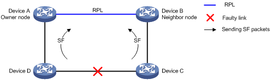
As shown in Figure 25, the link-down report mechanism uses the following process:
Device C and Device D detect the link failure and perform the following operations:
Block the ports on both side of the faulty link.
Periodically send SF packets to other nodes.
Device A and Device B receive the SF packets and perform the following operations:
Unblock RPL ports.
Update the MAC address entries.
Service packets are switched to the RPL link.
Link recovery mechanism
Figure 26: Link recovery mechanism
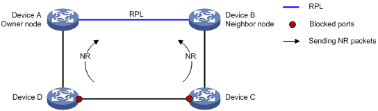
As shown in Figure 26, the link recovery mechanism uses the following process:
Device C and Device D detect the link recovery and perform the following operations:
Block the recovered ports.
Start the guard timer.
Send NR packets.
When Device A (owner node) receives the NR packets, it does not perform any operations if it is in non-revertive mode. If Device A is in revertive mode, it performs the following operations:
Starts the WTR timer.
Blocks the RPL port and periodically sends NR-RB packets when the WTR timer expires.
When other nodes receive the NR-RB packets, they perform the following operations:
Device B (neighbor port) blocks the RPL port.
Device C and Device D unblock the recovered ports.
Service packets are switched to the recovered link.
Multi-instance load balancing mechanism
Figure 27: Multi-instance load balancing mechanism
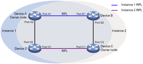
An ERPS ring topology might carry traffic from multiple VLANs. Traffic from different VLANs can be load balanced among different ERPS instances.
ERPS uses the following types of VLANs:
Control VLAN—Carries ERPS protocol packets. The system determines the control VLANs for ERPS ring member ports. Each ERPS instance has its own control VLAN.
Protected VLAN—Carries data packets. Each ERPS instance has its own protected VLAN. Protected VLANs are configured by using the mappings between VLANs and MSTIs.
As shown in Figure 27, the ERPS ring is configured with instance 1 and instance 2. For instance 1, the owner node is Device A, and the RPL is the link between Device A and Device B. For instance 2, the owner node is Device C, and the RPL is the link between Device C and Device D. Traffic from different VLANs can be load balanced among different links.
Manual configuration mechanism
ERPS supports the following manual configuration modes:
MS—Use the erps switch manual command to block an ERPS ring member port. A port in MS mode is blocked and sends MS packets. The nodes that receive the MS packets unblock available ports. If the nodes in MS mode receive an SF packet, they unblock the blocked ports.
FS—Use the erps switch force ring command to block an ERPS ring member port. A port in FS mode is blocked and sends FS packets. The nodes that receive the FS packets unblock available ports. If the nodes in FS mode receive an SF packet, they do not unblock the blocked ports.
Collaboration mechanism
To detect and clear link faults typically for a fiber link, use ERPS with CFD and Track. You can associate ERPS ring member ports with the continuity check function of CFD through track entries. CFD reports link events only when the monitored VLAN is the control VLAN of the ERPS instance for the port. For more information about CFD and Track, see "Configuring CFD" and "Configuring Track."