Example of STP calculation
Figure 25 provides an example showing how the STP algorithm works.
Figure 25: The STP algorithm
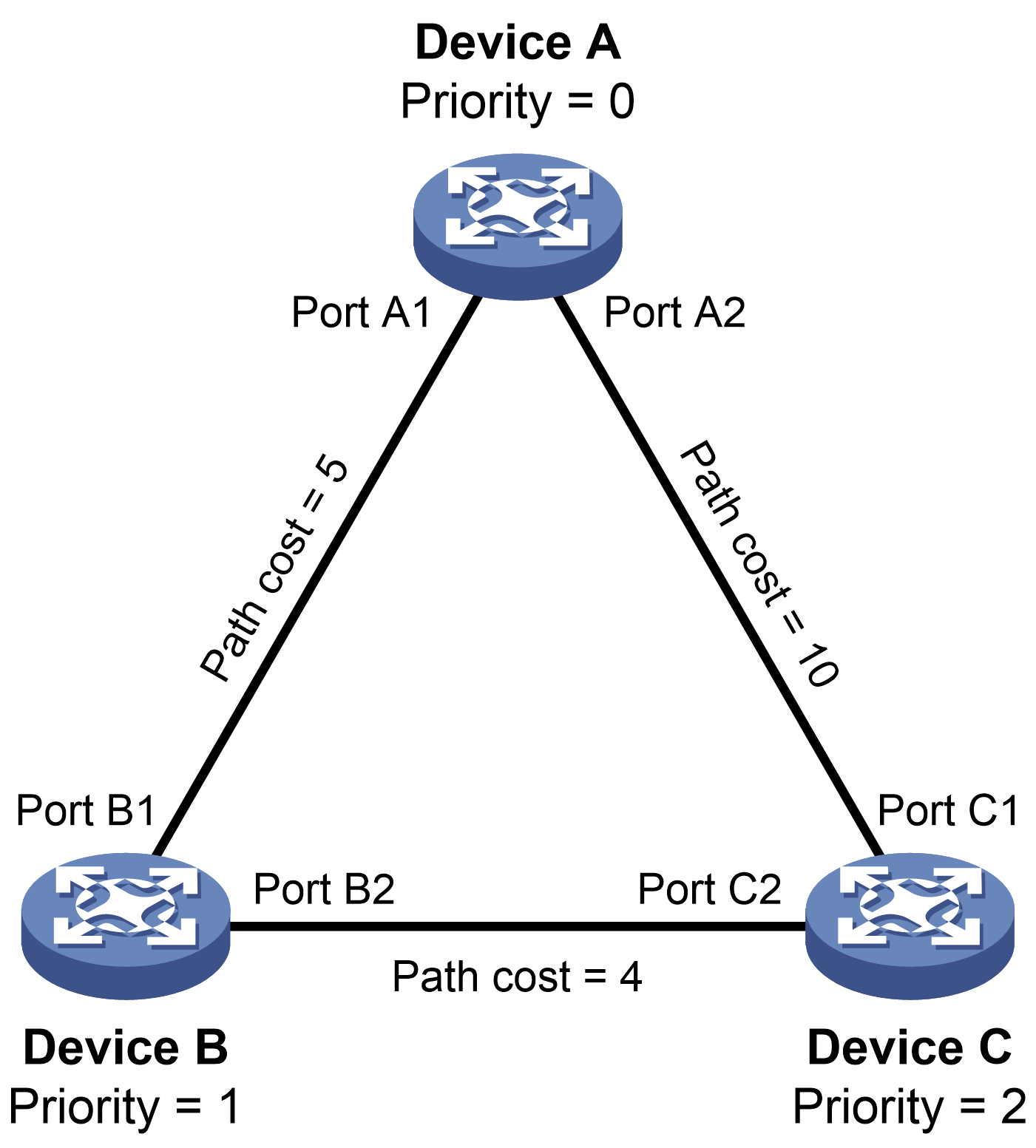
As shown in Figure 25, the priority values of Device A, Device B, and Device C are 0, 1, and 2, respectively. The path costs of links among the three devices are 5, 10, and 4.
Device state initialization
In Table 9, each configuration BPDU contains the following fields: root bridge ID, root path cost, designated bridge ID, and designated port ID.
Table 9: Initial state of each device
Device | Port name | Configuration BPDU on the port |
|---|---|---|
Device A | Port A1 | {0, 0, 0, Port A1} |
Port A2 | {0, 0, 0, Port A2} | |
Device B | Port B1 | {1, 0, 1, Port B1} |
Port B2 | {1, 0, 1, Port B2} | |
Device C | Port C1 | {2, 0, 2, Port C1} |
Port C2 | {2, 0, 2, Port C2} |
Configuration BPDUs comparison on each device
In Table 10, each configuration BPDU contains the following fields: root bridge ID, root path cost, designated bridge ID, and designated port ID.
Table 10: Comparison process and result on each device
Device | Comparison process | Configuration BPDU on ports after comparison |
|---|---|---|
Device A | Port A1 performs the following operations:
Port A2 performs the following operations:
Device A determines that it is both the root bridge and designated bridge in the configuration BPDUs of all its ports. It considers itself as the root bridge. It does not change the configuration BPDU of any port and starts to periodically send configuration BPDUs. |
|
Device B | Port B1 performs the following operations:
Port B2 performs the following operations:
|
|
Device B performs the following operations:
Based on the configuration BPDU and path cost of the root port, Device B calculates a designated port configuration BPDU for Port B2 {0, 5, 1, Port B2}. Device B compares it with the existing configuration BPDU of Port B2 {1, 0, 1, Port B2}. Device B determines that the calculated one is superior, and determines that Port B2 is the designated port. It replaces the configuration BPDU on Port B2 with the calculated one, and periodically sends the calculated configuration BPDU. |
| |
Device C | Port C1 performs the following operations:
Port C2 performs the following operations:
|
|
Device C performs the following operations:
Based on the configuration BPDU and path cost of the root port, Device C calculates the configuration BPDU of Port C2 {0, 10, 2, Port C2}. Device C compares it with the existing configuration BPDU of Port C2 {1, 0, 1, Port B2}. Device C determines that the calculated configuration BPDU is superior to the existing one, selects Port C2 as the designated port, and replaces the configuration BPDU of Port C2 with the calculated one. |
| |
Port C2 performs the following operations:
Port C1 performs the following operations:
|
| |
Device C determines that the root path cost of Port C1 is larger than that of Port C2. The root path cost of Port C1 is 10, root path cost of the received configuration BPDU (0) plus path cost of Port C1 (10). The root path cost of Port C2 is 9, root path cost of the received configuration BPDU (5) plus path cost of Port C2 (4). Device C determines that the configuration BPDU of Port C2 is the optimum, and selects Port C2 as the root port with the configuration BPDU unchanged. Based on the configuration BPDU and path cost of the root port, Device C performs the following operations:
Port C1 does not forward data until a new event triggers a spanning tree calculation process: for example, the link between Device B and Device C is down. |
|
Final calculated spanning tree
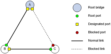
After the comparison processes described in Table 10, a spanning tree with Device A as the root bridge is established, as shown in Figure 26.
Figure 26: The final calculated spanning tree