NQA collaboration configuration example
Network requirements
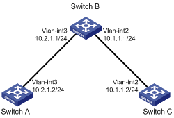
As shown in Figure 21, configure a static route to Switch C with Switch B as the next hop on Switch A. Associate the static route, a track entry, and an ICMP echo operation to monitor the state of the static route.
Figure 21: Network diagram
Configuration procedure
Assign IP addresses to interfaces, as shown in Figure 21. (Details not shown.)
On Switch A, configure a static route, and associate the static route with track entry 1.
<SwitchA> system-view
[SwitchA] ip route-static 10.1.1.2 24 10.2.1.1 track 1
On Switch A, configure an ICMP echo operation:
# Create an NQA operation with the administrator name admin and operation tag test1.
[SwitchA] nqa entry admin test1
# Configure the NQA operation type as ICMP echo.
[SwitchA-nqa-admin-test1] type icmp-echo
# Specify 10.2.1.1 as the destination IP address.
[SwitchA-nqa-admin-test1-icmp-echo] destination ip 10.2.1.1
# Configure the operation to repeat every 100 milliseconds.
[SwitchA-nqa-admin-test1-icmp-echo] frequency 100
# Create reaction entry 1. If the number of consecutive probe failures reaches 5, collaboration is triggered.
[SwitchA-nqa-admin-test1-icmp-echo] reaction 1 checked-element probe-fail threshold-type consecutive 5 action-type trigger-only
[SwitchA-nqa-admin-test1-icmp-echo] quit
# Start the ICMP operation.
[SwitchA] nqa schedule admin test1 start-time now lifetime forever
On Switch A, create track entry 1, and associate it with reaction entry 1 of the NQA operation.
[SwitchA] track 1 nqa entry admin test1 reaction 1
Verifying the configuration
# Display information about all the track entries on Switch A.
[SwitchA] display track all
Track ID: 1
  State: Positive
  Duration: 0 days 0 hours 0 minutes 0 seconds
  Notification delay: Positive 0, Negative 0 (in seconds)
  Tracked object:
    NQA entry: admin test1
    Reaction: 1
# Display brief information about active routes in the routing table on Switch A.
[SwitchA] display ip routing-table

Destinations : 13        Routes : 13

Destination/Mask    Proto  Pre  Cost         NextHop         Interface
0.0.0.0/32          Direct 0    0            127.0.0.1       InLoop0
10.1.1.0/24         Static 60   0            10.2.1.1        Vlan3
10.2.1.0/24         Direct 0    0            10.2.1.2        Vlan3
10.2.1.0/32         Direct 0    0            10.2.1.2        Vlan3
10.2.1.2/32         Direct 0    0            127.0.0.1       InLoop0
10.2.1.255/32       Direct 0    0            10.2.1.2        Vlan3
127.0.0.0/8         Direct 0    0            127.0.0.1       InLoop0
127.0.0.0/32        Direct 0    0            127.0.0.1       InLoop0
127.0.0.1/32        Direct 0    0            127.0.0.1       InLoop0
127.255.255.255/32  Direct 0    0            127.0.0.1       InLoop0
224.0.0.0/4         Direct 0    0            0.0.0.0         NULL0
224.0.0.0/24        Direct 0    0            0.0.0.0         NULL0
255.255.255.255/32  Direct 0    0            127.0.0.1       InLoop0
The output shows that the static route with the next hop 10.2.1.1 is active, and the status of the track entry is positive.
# Remove the IP address of VLAN-interface 3 on Switch B.
<SwitchB> system-view
[SwitchB] interface vlan-interface 3
[SwitchB-Vlan-interface3] undo ip address
# Display information about all the track entries on Switch A.
[SwitchA] display track all
Track ID: 1
  State: Negative
  Duration: 0 days 0 hours 0 minutes 0 seconds
  Notification delay: Positive 0, Negative 0 (in seconds)
  Tracked object:
    NQA entry: admin test1
    Reaction: 1
# Display brief information about active routes in the routing table on Switch A.
[SwitchA] display ip routing-table

Destinations : 12        Routes : 12

Destination/Mask    Proto  Pre  Cost         NextHop         Interface
0.0.0.0/32          Direct 0    0            127.0.0.1       InLoop0
10.2.1.0/24         Direct 0    0            10.2.1.2        Vlan3
10.2.1.0/32         Direct 0    0            10.2.1.2        Vlan3
10.2.1.2/32         Direct 0    0            127.0.0.1       InLoop0
10.2.1.255/32       Direct 0    0            10.2.1.2        Vlan3
127.0.0.0/8         Direct 0    0            127.0.0.1       InLoop0
127.0.0.0/32        Direct 0    0            127.0.0.1       InLoop0
127.0.0.1/32        Direct 0    0            127.0.0.1       InLoop0
127.255.255.255/32  Direct 0    0            127.0.0.1       InLoop0
224.0.0.0/4         Direct 0    0            0.0.0.0         NULL0
224.0.0.0/24        Direct 0    0            0.0.0.0         NULL0
255.255.255.255/32  Direct 0    0            127.0.0.1       InLoop0
The output shows that the static route does not exist, and the status of the track entry is negative.