Ping example
Network requirements
As shown in Figure 1, determine if Device A and Device C can reach each other. If they can reach each other, get detailed information about routes from Device A to Device C.
Figure 1: Network diagram
Configuration procedure
# Use the ping command on Device A to test connectivity to Device C.
Ping 1.1.2.2 (1.1.2.2): 56 data bytes, press CTRL_C to break
56 bytes from 1.1.2.2: icmp_seq=0 ttl=254 time=2.137 ms
56 bytes from 1.1.2.2: icmp_seq=1 ttl=254 time=2.051 ms
56 bytes from 1.1.2.2: icmp_seq=2 ttl=254 time=1.996 ms
56 bytes from 1.1.2.2: icmp_seq=3 ttl=254 time=1.963 ms
56 bytes from 1.1.2.2: icmp_seq=4 ttl=254 time=1.991 ms

--- Ping statistics for 1.1.2.2 ---
5 packet(s) transmitted, 5 packet(s) received, 0.0% packet loss
round-trip min/avg/max/std-dev = 1.963/2.028/2.137/0.062 ms
The output shows the following information:
Device A sends five ICMP packets to Device C and Device A receives five ICMP packets.
No ICMP packet is lost.
The route is reachable.
# Get detailed information about routes from Device A to Device C.
<DeviceA> ping -r 1.1.2.2
Ping 1.1.2.2 (1.1.2.2): 56 data bytes, press CTRL_C to break
56 bytes from 1.1.2.2: icmp_seq=0 ttl=254 time=4.685 ms
RR:      1.1.2.1
         1.1.2.2
         1.1.1.2
         1.1.1.1
56 bytes from 1.1.2.2: icmp_seq=1 ttl=254 time=4.834 ms  (same route)
56 bytes from 1.1.2.2: icmp_seq=2 ttl=254 time=4.770 ms  (same route)
56 bytes from 1.1.2.2: icmp_seq=3 ttl=254 time=4.812 ms  (same route)
56 bytes from 1.1.2.2: icmp_seq=4 ttl=254 time=4.704 ms  (same route)

--- Ping statistics for 1.1.2.2 ---
5 packet(s) transmitted, 5 packet(s) received, 0.0% packet loss
round-trip min/avg/max/std-dev = 4.685/4.761/4.834/0.058 ms
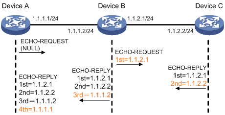
The test procedure of ping –r is as shown in Figure 1:
The source device (Device A) sends an ICMP echo request to the destination device (Device C) with the RR option blank.
The intermediate device (Device B) adds the IP address of its outbound interface (1.1.2.1) to the RR option of the ICMP echo request, and forwards the packet.
Upon receiving the request, the destination device copies the RR option in the request and adds the IP address of its outbound interface (1.1.2.2) to the RR option. Then the destination device sends an ICMP echo reply.
The intermediate device adds the IP address of its outbound interface (1.1.1.2) to the RR option in the ICMP echo reply, and then forwards the reply.
Upon receiving the reply, the source device adds the IP address of its inbound interface (1.1.1.1) to the RR option. The detailed information of routes from Device A to Device C is formatted as: 1.1.1.1 <-> {1.1.1.2; 1.1.2.1} <-> 1.1.2.2.