LACP MAD-enabled IRF configuration example
Network requirements
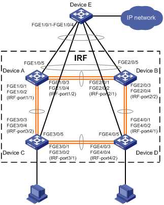
As shown in Figure 14, set up a four-chassis IRF fabric at the access layer of the enterprise network.
Configure LACP MAD on the multichassis aggregation to Device E, an HPE device that supports extended LACP.
Figure 14: Network diagram
Configuration procedure
Configure Device A:
# Shut down the physical interfaces used for IRF links. In this example, the physical interfaces are shut down in batch. For more information, see Layer 2—LAN Switching Configuration Guide.
<Sysname> system-view
[Sysname] interface range fortygige 1/0/1 to fortygige 1/0/4
[Sysname-if-range] shutdown
[Sysname-if-range] quit
# Bind FortyGigE 1/0/1 and FortyGigE 1/0/2 to IRF-port 1/1.
[Sysname] irf-port 1/1
[Sysname-irf-port1/1] port group interface fortygige 1/0/1
[Sysname-irf-port1/1] port group interface fortygige 1/0/2
[Sysname-irf-port1/1] quit
# Bind FortyGigE 1/0/3 and FortyGigE 1/0/4 to IRF-port 1/2.
[Sysname] irf-port 1/2
[Sysname-irf-port1/2] port group interface fortygige 1/0/3
[Sysname-irf-port1/2] port group interface fortygige 1/0/4
[Sysname-irf-port1/2] quit
# Bring up the physical interfaces and save the configuration.
[Sysname] interface range fortygige 1/0/1 to fortygige 1/0/4
[Sysname-if-range] undo shutdown
[Sysname-if-range] quit
[Sysname] save
# Activate the IRF port configuration.
[Sysname] irf-port-configuration active
Configure Device B:
# Change the member ID of Device B to 2 and reboot the device to validate the change.
<Sysname> system-view
[Sysname] irf member 1 renumber 2
Renumbering the member ID may result in configuration change or loss. Continue? [Y/N]:y
[Sysname] quit
<Sysname> reboot
# Connect Device B to Device A as shown in Figure 14, and log in to Device B. (Details not shown.)
# Shut down the physical interfaces for IRF links.
<Sysname> system-view
[Sysname] interface range fortygige 2/0/1 to fortygige 2/0/4
[Sysname-if-range] shutdown
[Sysname-if-range] quit
# Bind FortyGigE 2/0/1 and FortyGigE 2/0/2 to IRF-port 2/1.
[Sysname] irf-port 2/1
[Sysname-irf-port2/1] port group interface fortygige 2/0/1
[Sysname-irf-port2/1] port group interface fortygige 2/0/2
[Sysname-irf-port2/1] quit
# Bind FortyGigE 2/0/3 and FortyGigE 2/0/4 to IRF-port 2/2.
[Sysname] irf-port 2/2
[Sysname-irf-port2/2] port group interface fortygige 2/0/3
[Sysname-irf-port2/2] port group interface fortygige 2/0/4
[Sysname-irf-port2/2] quit
# Bring up the physical interfaces and save the configuration.
[Sysname] interface range fortygige 2/0/1 to fortygige 2/0/4
[Sysname-if-range] undo shutdown
[Sysname-if-range] quit
[Sysname] save
# Activate the IRF port configuration.
[Sysname] irf-port-configuration active
The two devices perform master election, and the one that has lost the election reboots to form an IRF fabric with the master.
Configure Device C:
# Change the member ID of Device C to 3 and reboot the device to validate the change.
<Sysname> system-view
[Sysname] irf member 1 renumber 3
Renumbering the member ID may result in configuration change or loss. Continue? [Y/N]:y
[Sysname] quit
<Sysname> reboot
# Connect Device C to Device A as shown in Figure 14, and log in to Device C. (Details not shown.)
# Shut down the physical interfaces for IRF links.
<Sysname> system-view
[Sysname] interface range fortygige 3/0/1 to fortygige 3/0/4
[Sysname-if-range] shutdown
[Sysname-if-range] quit
# Bind FortyGigE 3/0/1 and FortyGigE 3/0/2 to IRF-port 3/1.
[Sysname] irf-port 3/1
[Sysname-irf-port3/1] port group interface fortygige 3/0/1
[Sysname-irf-port3/1] port group interface fortygige 3/0/2
[Sysname-irf-port3/1] quit
# Bind FortyGigE 3/0/3 and FortyGigE 3/0/4 to IRF-port 3/2.
[Sysname] irf-port 3/2
[Sysname-irf-port3/2] port group interface fortygige 3/0/3
[Sysname-irf-port3/2] port group interface fortygige 3/0/4
[Sysname-irf-port3/2] quit
# Bring up the physical interfaces and save the configuration.
[Sysname] interface range fortygige 3/0/1 to fortygige 3/0/4
[Sysname-if-range] undo shutdown
[Sysname-if-range] quit
[Sysname] save
# Activate the IRF port configuration.
[Sysname] irf-port-configuration active
Device C reboots to join the IRF fabric.
Configure Device D:
# Change the member ID of Device D to 4 and reboot the device to validate the change.
<Sysname> system-view
[Sysname] irf member 1 renumber 4
Renumbering the member ID may result in configuration change or loss. Continue? [Y/N]:y
[Sysname] quit
<Sysname> reboot
# Connect Device D to Device B and Device C as shown in Figure 14, and log in to Device D. (Details not shown.)
# Shut down the physical interfaces.
<Sysname> system-view
[Sysname] interface range fortygige 4/0/1 to fortygige 4/0/4
[Sysname-if-range] shutdown
[Sysname-if-range] quit
# Bind FortyGigE 4/0/1 and FortyGigE 4/0/2 to IRF-port 4/1.
[Sysname] irf-port 4/1
[Sysname-irf-port4/1] port group interface fortygige 4/0/1
[Sysname-irf-port4/1] port group interface fortygige 4/0/2
[Sysname-irf-port4/1] quit
# Bind FortyGigE 4/0/3 and FortyGigE 4/0/4 to IRF-port 4/2.
[Sysname] irf-port 4/2
[Sysname-irf-port4/2] port group interface fortygige 4/0/3
[Sysname-irf-port4/2] port group interface fortygige 4/0/4
[Sysname-irf-port4/2] quit
# Bring up the physical interfaces and save the configuration.
[Sysname] interface range fortygige 4/0/1 to fortygige 4/0/4
[Sysname-if-range] undo shutdown
[Sysname-if-range] quit
[Sysname] save
# Activate the IRF port configuration.
[Sysname] irf-port-configuration active
Device D reboots to join the IRF fabric. A four-chassis IRF fabric is formed.
Configure LACP MAD on the IRF fabric:
# Set the domain ID of the IRF fabric to 1.
<Sysname> system-view
[Sysname] irf domain 1
# Create a dynamic aggregate interface and enable LACP MAD.
[Sysname] interface bridge-aggregation 2
[Sysname-Bridge-Aggregation2] link-aggregation mode dynamic
[Sysname-Bridge-Aggregation2] mad enable
You need to assign a domain ID (range: 0-4294967295)
[Current domain is: 1]:
 The assigned  domain ID is: 1
 Info: MAD LACP only enable on dynamic aggregation interface.
[Sysname-Bridge-Aggregation2] quit
# Assign FortyGigE 1/0/5, FortyGigE 2/0/5, FortyGigE 3/0/5, and FortyGigE 4/0/5 to the aggregate interface.
[Sysname] interface range fortygige 1/0/5 fortygige 2/0/5 fortygige 3/0/5 fortygige 4/0/5
[Sysname-if-range] port link-aggregation group 2
[Sysname-if-range] quit
Configure Device E as the intermediate device:
![[CAUTION: ]](images/caution.png)
CAUTION:
If the intermediate device is also an IRF fabric, assign the two IRF fabrics different domain IDs for correct split detection. False detection causes IRF split.
# Create a dynamic aggregate interface.
<Sysname> system-view
[Sysname] interface bridge-aggregation 2
[Sysname-Bridge-Aggregation2] link-aggregation mode dynamic
[Sysname-Bridge-Aggregation2] quit
# Assign FortyGigE 1/0/1, FortyGigE 1/0/2, FortyGigE 1/0/3, and FortyGigE 1/0/4 to the aggregate interface.
[Sysname] interface range fortygige 1/0/1 to fortygige 1/0/4
[Sysname-if-range] port link-aggregation group 2
[Sysname-if-range] quit