VLAN mapping implementations
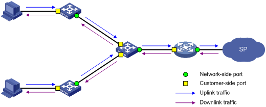
Figure 81 shows a simplified network that illustrates basic VLAN mapping terms.
Basic VLAN mapping terms include the following:
Uplink traffic—Traffic transmitted from the customer network to the service provider network.
Downlink traffic—Traffic transmitted from the service provider network to the customer network.
Network-side port—A port connected to or closer to the service provider network.
Customer-side port—A port connected to or closer to the customer network.
Figure 81: Basic VLAN mapping terms
One-to-one VLAN mapping
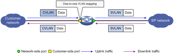
As shown in Figure 82, one-to-one VLAN mapping is implemented on the customer-side port and replaces VLAN tags as follows:
Replaces the CVLAN with the SVLAN for the uplink traffic.
Replaces the SVLAN with the CVLAN for the downlink traffic.
Figure 82: One-to-one VLAN mapping implementation
Many-to-one VLAN mapping
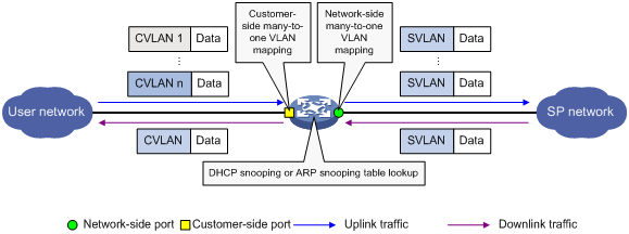
As shown in Figure 83, many-to-one VLAN mapping is implemented on both the customer-side and network-side ports as follows:
For the uplink traffic, the customer-side many-to-one VLAN mapping replaces multiple CVLANs with the same SVLAN.
For the downlink traffic, the network-side many-to-one VLAN mapping replaces the SVLAN with the CVLAN found in the DHCP or ARP snooping table. For more information about DHCP and ARP snooping, see Layer 3—IP Services Configuration Guide.
Figure 83: Many-to-one VLAN mapping implementation
One-to-two VLAN mapping
As shown in Figure 84, one-to-two VLAN mapping is implemented on the customer-side port to add the SVLAN tag for the uplink traffic.
For the downlink traffic to be correctly sent to the customer network, make sure the SVLAN tag is removed on the customer-side port before transmission. Use one of the following methods to remove the SVLAN tag from the downlink traffic:
Configure the customer-side port as a hybrid port and assign the port to the SVLAN as an untagged member.
Configure the customer-side port as a trunk port and set the port PVID to the SVLAN.
Figure 84: One-to-two VLAN mapping implementation

Two-to-two VLAN mapping
As shown in Figure 85, two-to-two VLAN mapping is implemented on the customer-side port and replaces VLAN tags as follows:
Replaces the CVLAN and the SVLAN with the CVLAN' and the SVLAN' for the uplink traffic.
Replaces the SVLAN' and CVLAN' with the SVLAN and the CVLAN for the downlink traffic.
Figure 85: Two-to-two VLAN mapping implementation
