Example for configuring Kompella MPLS L2VPN
Network requirements
CEs are connected to PEs through VLAN interfaces.
Establish a Kompella VC, so CE 1 and CE 2 can exchange Layer 2 packets across the backbone.
Figure 59: Network diagram
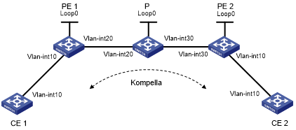
Device | Interface | IP address | Device | Interface | IP address |
CE 1 | Vlan-int10 | 100.1.1.1/24 | CE 2 | Vlan-int10 | 100.1.1.2/24 |
PE 1 | Loop0 | 2.2.2.2/32 | P | Loop0 | 3.3.3.3/32 |
Vlan-int20 | 10.1.1.1/24 | Vlan-int20 | 10.1.1.2/24 | ||
PE 2 | Loop0 | 4.4.4.4/32 | Vlan-int30 | 10.2.2.2/24 | |
Vlan-int30 | 10.2.2.1/24 |
Configuration procedure
Configure an IGP on the MPLS backbone.
This example uses OSPF. (Details not shown.)
After OSPF configuration is complete, execute the display ip routing-table command on each LSR. You should see that the LSR has learned the routes to the LSR IDs of the other LSRs. Execute the display ospf peer command. You should see that OSPF adjacencies have been established and reached Full state.
Configure basic MPLS and LDP to establish LDP LSPs. (Details not shown.)
After configuration, execute the display mpls ldp session and display mpls ldp peer commands to display the LDP sessions and peer relationship established, or the display mpls lsp command to display the LSPs established.
Configure BGP L2VPN capability:
# Configure PE 1.
<Sysname> system-view
[Sysname] sysname PE1
[PE1] l2vpn
[PE1-l2vpn] mpls l2vpn
[PE1-l2vpn] quit
[PE1] bgp 100
[PE1-bgp] peer 4.4.4.4 as-number 100
[PE1-bgp] peer 4.4.4.4 connect-interface loopback 0
[PE1-bgp] l2vpn-family
[PE1-bgp-af-l2vpn] policy vpn-target
[PE1-bgp-af-l2vpn] peer 4.4.4.4 enable
[PE1-bgp-af-l2vpn] quit
[PE1-bgp] quit
# Configure PE 2.
<Sysname> system-view
[Sysname] sysname PE2
[PE2] l2vpn
[PE2-l2vpn] mpls l2vpn
[PE2-l2vpn] quit
[PE2] bgp 100
[PE2-bgp] peer 2.2.2.2 as-number 100
[PE2-bgp] peer 2.2.2.2 connect-interface loopback 0
[PE2-bgp] l2vpn-family
[PE2-bgp-af-l2vpn] policy vpn-target
[PE2-bgp-af-l2vpn] peer 2.2.2.2 enable
[PE2-bgp-af-l2vpn] quit
[PE2-bgp] quit
After completing the configurations, execute the display bgp l2vpn peer command on PE 1 and PE 2 to display the peer relationship established between the PEs. The peer state should be Established. Take PE 1 as an example:
[PE1] display bgp l2vpn peer
BGP local router ID : 2.2.2.2
 Local AS number : 100
 Total number of peers : 1                 Peers in established state : 1
  Peer      V   AS   MsgRcvd   MsgSent  OutQ PrefRcv Up/Down  State
  4.4.4.4   4   100        2        5     0       0  00:01:07 Established
Configure the L2VPN and the CE connection:
# Configure PE 1. The configurations of the VLAN interfaces are similar to those for Martini MPLS L2VPN and are omitted.
[PE1] mpls l2vpn vpn1 encapsulation vlan
[PE1-mpls-l2vpn-vpn1] route-distinguisher 100:1
[PE1-mpls-l2vpn-vpn1] vpn-target 1:1
[PE1-mpls-l2vpn-vpn1] ce ce1 id 1 range 10
[PE1-mpls-l2vpn-ce-vpn1-ce1] connection ce-offset 2 interface vlan-interface 10
[PE1-mpls-l2vpn-ce-vpn1-ce1] quit
[PE1-mpls-l2vpn-vpn1] quit
# Configure PE 2.
[PE2] mpls l2vpn vpn1 encapsulation vlan
[PE2-mpls-l2vpn-vpn1] route-distinguisher 100:1
[PE2-mpls-l2vpn-vpn1] vpn-target 1:1
[PE2-mpls-l2vpn-vpn1] ce ce2 id 2 range 10
[PE2-mpls-l2vpn-ce-vpn1-ce2] connection ce-offset 1 interface vlan-interface 10
[PE2-mpls-l2vpn-ce-vpn1-ce2] quit
[PE2-mpls-l2vpn-vpn1] quit
Verify the configuration:
# Execute the display mpls l2vpn connection command on the PEs. The output shows that a VC in up state has been established between the PEs. Take PE 1 as an example:
Display the MPLS L2VPN connection information on PE 1.
[PE1] display mpls l2vpn connection
1 total connections,
connections: 1 up, 0 down, 0 local, 1 remote, 0 unknown
VPN name: vpn1,
1 total connections,
connections: 1 up, 0 down, 0 local, 1 remote, 0 unknown
  CE name: ce1, id: 1,
  Rid type status peer-id         route-distinguisher   intf
  2   rmt  up     4.4.4.4         100:1                 Vlan10
# Ping CE 2 from CE 1. The output shows that CE 1 and CE 2 can ping each other.
[CE1] ping 100.1.1.2
  PING 100.1.1.2: 56  data bytes, press CTRL_C to break
    Reply from 100.1.1.2: bytes=56 Sequence=1 ttl=255 time=90 ms
    Reply from 100.1.1.2: bytes=56 Sequence=2 ttl=255 time=77 ms
    Reply from 100.1.1.2: bytes=56 Sequence=3 ttl=255 time=34 ms
    Reply from 100.1.1.2: bytes=56 Sequence=4 ttl=255 time=46 ms
    Reply from 100.1.1.2: bytes=56 Sequence=5 ttl=255 time=94 ms
  --- 100.1.1.2 ping statistics ---
    5 packet(s) transmitted
    5 packet(s) received
    0.00% packet loss
    round-trip min/avg/max = 34/68/94 ms