Example for configuring Martini MPLS L2VPN
Network requirements
CEs are connected to PEs through VLAN interfaces.
Establish a Martini VC, so CE 1 and CE 2 can exchange Layer 2 packets across the backbone.
Figure 58: Network diagram
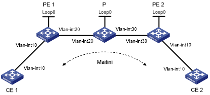
Device | Interface | IP address | Device | Interface | IP address |
CE 1 | Vlan-int10 | 100.1.1.1/24 | CE 2 | Vlan-int10 | 100.1.1.2/24 |
PE 1 | Loop0 | 192.2.2.2/32 | P | Loop0 | 192.4.4.4/32 |
Vlan-int20 | 10.1.1.1/24 | Vlan-int20 | 10.1.1.2/24 | ||
PE 2 | Loop0 | 192.3.3.3/32 | Vlan-int30 | 10.2.2.2/24 | |
Vlan-int30 | 10.2.2.1/24 |
Configuration procedure
Configure CE 1:
# Configure an IP address for the interface connected to PE 1.
<Sysname> system-view
[Sysname] sysname CE1
[CE1] interface vlan-interface 10
[CE1-Vlan-interface10] ip address 100.1.1.1 24
Configure PE 1:
# Configure the LSR ID and enable MPLS globally.
<Sysname> system-view
[Sysname] sysname PE1
[PE1] interface loopback 0
[PE1-LoopBack0] ip address 192.2.2.2 32
[PE1-LoopBack0] quit
[PE1] mpls lsr-id 192.2.2.2
[PE1] mpls
[PE1-mpls] quit
# Enable L2VPN and MPLS L2VPN.
[PE1] l2vpn
[PE1-l2vpn] mpls l2vpn
[PE1-l2vpn] quit
# Enable LDP globally.
[PE1] mpls ldp
[PE1-mpls-ldp] quit
# Establish a remote session between PE 1 and PE 2.
[PE1] mpls ldp remote-peer 1
[PE1-mpls-ldp-remote-1] remote-ip 192.3.3.3
[PE1-mpls-ldp-remote-1] quit
# Configure the interface connected with the P device, and enable LDP on the interface.
[PE1] interface vlan-interface 20
[PE1-Vlan-interface20] ip address 10.1.1.1 24
[PE1-Vlan-interface20] mpls
[PE1-Vlan-interface20] mpls ldp
[PE1-Vlan-interface20] quit
# Configure OSPF on PE 1 for establishing LSPs.
[PE1] ospf
[PE1-ospf-1] area 0
[PE1-ospf-1-area-0.0.0.0] network 10.1.1.1 0.0.0.255
[PE1-ospf-1-area-0.0.0.0] network 192.2.2.2 0.0.0.0
[PE1-ospf-1-area-0.0.0.0] quit
[PE1-ospf-1] quit
# Create a Martini VC on the interface connected to CE 1. The interface requires no IP address.
[PE1] interface vlan-interface 10
[PE1-Vlan-interface10] mpls l2vc 192.3.3.3 101
[PE1-Vlan-interface10] quit
Configure the P device:
# Configure the LSR ID and enable MPLS globally.
<Sysname> system-view
[Sysname] sysname P
[P] interface loopback 0
[P-LoopBack0] ip address 192.4.4.4 32
[P-LoopBack0] quit
[P] mpls lsr-id 192.4.4.4
[P] mpls
[P-mpls] quit
# Enable LDP globally.
[P] mpls ldp
[P-mpls-ldp] quit
# Configure the interface connected with PE 1, and enable LDP on the interface.
[P] interface vlan-interface 20
[P-Vlan-interface20] ip address 10.1.1.2 24
[P-Vlan-interface20] mpls
[P-Vlan-interface20] mpls ldp
[P-Vlan-interface20] quit
# Configure the interface connected with PE 2, and enable LDP on the interface.
[P] interface vlan-interface 30
[P-Vlan-interface30] ip address 10.2.2.2 24
[P-Vlan-interface30] mpls
[P-Vlan-interface30] mpls ldp
[P-Vlan-interface30] quit
# Configure OSPF on the P device for establishing LSPs.
[P] ospf
[P-ospf-1] area 0
[P-ospf-1-area-0.0.0.0] network 10.1.1.2 0.0.0.255
[P-ospf-1-area-0.0.0.0] network 10.2.2.2 0.0.0.255
[P-ospf-1-area-0.0.0.0] network 192.4.4.4 0.0.0.0
[P-ospf-1-area-0.0.0.0] quit
[P-ospf-1] quit
Configure PE 2:
# Configure the LSR ID and enable MPLS globally.
<Sysname> system-view
[Sysname] sysname PE2
[PE2] interface loopback 0
[PE2-LoopBack0] ip address 192.3.3.3 32
[PE2-LoopBack0] quit
[PE2] mpls lsr-id 192.3.3.3
[PE2] mpls
[PE2-mpls] quit
# Enable L2VPN and MPLS L2VPN.
[PE2] l2vpn
[PE2-l2vpn] mpls l2vpn
[PE2-l2vpn] quit
# Enable LDP globally.
[PE2] mpls ldp
[PE2-mpls-ldp] quit
# Configure an LDP remote session between PE 2 and PE 1.
[PE2] mpls ldp remote-peer 2
[PE2-mpls-ldp-remote-2] remote-ip 192.2.2.2
[PE2-mpls-ldp-remote-2] quit
# Configure the interface connected with the P device, and enable LDP on the interface.
[PE2] interface vlan-interface 30
[PE2-Vlan-interface30] ip address 10.2.2.1 24
[PE2-Vlan-interface30] mpls
[PE2-Vlan-interface30] mpls ldp
[PE2-Vlan-interface30] quit
# Configure OSPF on PE 2 for establishing LSPs.
[PE2] ospf
[PE2-ospf-1] area 0
[PE2-ospf-1-area-0.0.0.0] network 192.3.3.3 0.0.0.0
[PE2-ospf-1-area-0.0.0.0] network 10.2.2.0 0.0.0.255
[PE2-ospf-1-area-0.0.0.0] quit
[PE2-ospf-1] quit
# Create a L2VPN connection on the interface connected to CE 2. The interface requires no IP address.
[PE2] interface vlan-interface 10
[PE2-Vlan-interface10] mpls l2vc 192.2.2.2 101
[PE2-Vlan-interface10] quit
Configure CE 2:
# Configure an IP address for the interface connected to PE 2.
<Sysname> system-view
[Sysname] sysname CE2
[CE2] interface vlan-interface 10
[CE2-Vlan-interface10] ip address 100.1.1.2 24
Verify the configuration:
# Display VC information on PE 1. The output shows that a VC has been established.
[PE1] display mpls l2vc
Total ldp vc : 1     1 up       0 down      0 blocked

Transport   Client               Service  VC       Local     Remote
VC ID       Intf                 ID       State    VC Label  VC Label
101         Vlan10               --       up       8193      8192
# Display VC information on PE 2. The output shows that a VC has been established.
[PE2] display mpls l2vc
Total ldp vc : 1     1 up       0 down      0 blocked

Transport   Client               Service  VC       Local     Remote
VC ID       Intf                 ID       State    VC Label  VC Label
101         Vlan10               --       up       8192      8193
# Ping CE 2 from CE 1. The output shows that CE 1 and CE 2 can ping each other.
[CE1] ping 100.1.1.2
  PING 100.1.1.2: 56  data bytes, press CTRL_C to break
    Reply from 100.1.1.2: bytes=56 Sequence=1 ttl=255 time=30 ms
    Reply from 100.1.1.2: bytes=56 Sequence=2 ttl=255 time=60 ms
    Reply from 100.1.1.2: bytes=56 Sequence=3 ttl=255 time=50 ms
    Reply from 100.1.1.2: bytes=56 Sequence=4 ttl=255 time=40 ms
    Reply from 100.1.1.2: bytes=56 Sequence=5 ttl=255 time=70 ms
  --- 100.1.1.2 ping statistics ---
    5 packet(s) transmitted
    5 packet(s) received
    0.00% packet loss
    round-trip min/avg/max = 30/50/70 ms