Configuration example
Network requirements
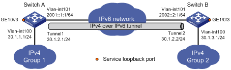
As shown in Figure 92, the two subnets Group 1 and Group 2 are connected over an IPv6 network. Configure an IPv4 over IPv6 tunnel between Switch A and Switch B to make the two subnets reachable to each other.
Figure 92: Network diagram
Configuration procedure
Before configuring an IPv4 over IPv6 tunnel, make sure Switch A and Switch B have the corresponding VLAN interfaces created and can reach each other.
Configure Switch A:
# Enable IPv6.
<SwitchA> system-view
[SwitchA] ipv6
# Specify an IPv4 address for VLAN-interface 100.
[SwitchA] interface vlan-interface 100
[SwitchA-Vlan-interface100] ip address 30.1.1.1 255.255.255.0
[SwitchA-Vlan-interface100] quit
# Specify an IPv6 address for VLAN-interface 101, the physical interface of the tunnel.
[SwitchA] interface vlan-interface 101
[SwitchA-Vlan-interface101] ipv6 address 2001::1:1 64
[SwitchA-Vlan-interface101] quit
# Create service loopback group 1 to support the tunnel service.
[SwitchA] service-loopback group 1 type tunnel
# Assign GigabitEthernet 1/0/3 to service loopback group 1, and disable STP, NDP, and LLDP.
[SwitchA] interface GigabitEthernet 1/0/3
[SwitchA-GigabitEthernet1/0/3] undo stp enable
[SwitchA-GigabitEthernet1/0/3] undo ndp enable
[SwitchA-GigabitEthernet1/0/3] undo lldp enable
[SwitchA-GigabitEthernet1/0/3] port service-loopback group 1
[SwitchA-GigabitEthernet1/0/3] quit
# Create interface Tunnel 1.
[SwitchA] interface tunnel 1
# Specify an IPv4 address for interface Tunnel 1.
[SwitchA-Tunnel1] ip address 30.1.2.1 255.255.255.0
# Configure the tunnel encapsulation mode.
[SwitchA-Tunnel1] tunnel-protocol ipv4-ipv6
# Specify the IP address of VLAN-interface 101 as the source address for interface Tunnel 1.
[SwitchA-Tunnel1] source 2001::1:1
# Specify the IP address of VLAN-interface 101 on Switch B as the destination address of interface Tunnel 1.
[SwitchA-Tunnel1] destination 2002::2:1
# Reference service loopback group 1 on the tunnel.
[SwitchA-Tunnel1] service-loopback-group 1
[SwitchA-Tunnel1] quit
# Configure a static route from Switch A through interface Tunnel 1 to Group 2.
[SwitchA] ip route-static 30.1.3.0 255.255.255.0 tunnel 1
Configure Switch B:
# Enable IPv6.
<SwitchB> system-view
[SwitchB] ipv6
# Specify an IPv4 address for VLAN-interface 100.
[SwitchB] interface vlan-interface 100
[SwitchB-Vlan-interface100] ip address 30.1.3.1 255.255.255.0
[SwitchB-Vlan-interface100] quit
# Specify an IPv6 address for VLAN-interface 101, the physical interface of the tunnel.
[SwitchB] interface vlan-interface 101
[SwitchB-Vlan-interface101] ipv6 address 2002::2:1 64
[SwitchB-Vlan-interface101] quit
# Create service loopback group 1 to support the tunnel service.
[SwitchB] service-loopback group 1 type tunnel
# Assign GigabitEthernet 1/0/3 to service loopback group 1, and disable STP, NDP, and LLDP on the interface.
[SwitchB] interface GigabitEthernet 1/0/3
[SwitchB-GigabitEthernet1/0/3] undo stp enable
[SwitchB-GigabitEthernet1/0/3] undo ndp enable
[SwitchB-GigabitEthernet1/0/3] undo lldp enable
[SwitchB-GigabitEthernet1/0/3] port service-loopback group 1
[SwitchB-GigabitEthernet1/0/3] quit
# Create interface Tunnel 2.
[SwitchB] interface tunnel 2
# Specify an IPv4 address for interface Tunnel 2.
[SwitchB-Tunnel2] ip address 30.1.2.2 255.255.255.0
# Configure the tunnel encapsulation mode.
[SwitchB-Tunnel2] tunnel-protocol ipv4-ipv6
# Specify the IP address of VLAN-interface 101 as the source address for interface Tunnel 2.
[SwitchB-Tunnel2] source 2002::2:1
# Specify the IP address of VLAN-interface 101 on Switch A as the destination address for interface Tunnel 2.
[SwitchB-Tunnel2] destination 2001::1:1
# Reference service loopback group 1 on the tunnel.
[SwitchB-Tunnel2] service-loopback-group 1
[SwitchB-Tunnel2] quit
# Configure a static route from Switch B through interface Tunnel 2 to Group 1.
[SwitchB] ip route-static 30.1.1.0 255.255.255.0 tunnel 2
Verifying the configuration
Display the status of the tunnel interfaces on Switch A and Switch B.
[SwitchA] display interface tunnel 1
Tunnel1 current state: UP
Line protocol current state: UP
Description: Tunnel1 Interface
The Maximum Transmit Unit is 1460
Internet Address is 30.1.2.1/24 Primary
Encapsulation is TUNNEL, service-loopback-group ID is 1.
Tunnel source 2002::0001:0001, destination 2002::0002:0001
Tunnel bandwidth 64 (kbps)
Tunnel protocol/transport IP/IPv6
Last clearing of counters:  Never
    Last 300 seconds input:  0 bytes/sec, 0 packets/sec
    Last 300 seconds output:  0 bytes/sec, 0 packets/sec
    152 packets input,  9728 bytes
    0 input error
    168 packets output,  10752 bytes
    0 output error

[SwitchB] display interface tunnel 2
Tunnel2 current state: UP
Line protocol current state: UP
Description: Tunnel2 Interface
The Maximum Transmit Unit is 1460
Internet Address is 30.1.2.2/24 Primary
Encapsulation is TUNNEL, service-loopback-group ID is 1.
Tunnel source 2002::0002:0001, destination 2002::0001:0001
Tunnel bandwidth 64 (kbps)
Tunnel protocol/transport IP/IPv6
    Last 300 seconds input:  1 bytes/sec, 0 packets/sec
    Last 300 seconds output:  1 bytes/sec, 0 packets/sec
    167 packets input,  10688 bytes
    0 input error
    170 packets output,  10880 bytes
    0 output error
# Ping the IPv4 address of the peer interface VLAN-interface 100 from Switch A.
[RouterA] ping 30.1.3.1
  PING 30.1.3.1: 56  data bytes, press CTRL_C to break
    Reply from 30.1.3.1: bytes=56 Sequence=1 ttl=255 time=46 ms
    Reply from 30.1.3.1: bytes=56 Sequence=2 ttl=255 time=15 ms
    Reply from 30.1.3.1: bytes=56 Sequence=3 ttl=255 time=16 ms
    Reply from 30.1.3.1: bytes=56 Sequence=4 ttl=255 time=15 ms
    Reply from 30.1.3.1: bytes=56 Sequence=5 ttl=255 time=16 ms

  --- 30.1.3.1 ping statistics ---
    5 packet(s) transmitted
    5 packet(s) received
    0.00% packet loss
    round-trip min/avg/max = 15/21/46 ms