Configuration example
Network requirements
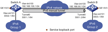
As shown in Figure 88, two IPv6 networks are connected over an IPv4 network. Configure an IPv6 over IPv4 tunnel between Switch A and Switch B to make the two IPv6 networks reachable to each other. If the destination IPv4 address cannot be automatically obtained from the destination IPv6 addresses of packets, configure an IPv6 manual tunnel.
Figure 88: Network diagram
Configuration procedure
Before configuring an IPv6 manual tunnel, make sure Switch A and Switch B have the corresponding VLAN interfaces created and can reach to each other.
Configure Switch A:
# Enable IPv6.
<SwitchA> system-view
[SwitchA] ipv6
# Specify an IPv4 address for VLAN-interface 100.
[SwitchA] interface vlan-interface 100
[SwitchA-Vlan-interface100] ip address 192.168.100.1 255.255.255.0
[SwitchA-Vlan-interface100] quit
# Specify an IPv6 address for VLAN-interface 101.
[SwitchA] interface vlan-interface 101
[SwitchA-Vlan-interface101] ipv6 address 3002::1 64
[SwitchA-Vlan-interface101] quit
# Create service loopback group 1 to support the tunnel service.
[SwitchA] service-loopback group 1 type tunnel
# Assign GigabitEthernet 1/0/3 to service loopback group 1, and disable STP, NDP, and LLDP on the interface.
[SwitchA] interface GigabitEthernet 1/0/3
[SwitchA-GigabitEthernet1/0/3] undo stp enable
[SwitchA-GigabitEthernet1/0/3] undo ndp enable
[SwitchA-GigabitEthernet1/0/3] undo lldp enable
[SwitchA-GigabitEthernet1/0/3] port service-loopback group 1
[SwitchA-GigabitEthernet1/0/3] quit
# Configure a manual IPv6 tunnel.
[SwitchA] interface tunnel 0
[SwitchA-Tunnel0] ipv6 address 3001::1/64
[SwitchA-Tunnel0] source vlan-interface 100
[SwitchA-Tunnel0] destination 192.168.50.1
[SwitchA-Tunnel0] tunnel-protocol ipv6-ipv4
# Reference service loopback group 1 on the tunnel.
[SwitchA-Tunnel0] service-loopback-group 1
[SwitchA-Tunnel0] quit
# Configure a static route to IPv6 Group 2 through Tunnel 0 on Switch A.
[SwitchA] ipv6 route-static 3003:: 64 tunnel 0
Configure Switch B
# Enable IPv6.
<SwitchB> system-view
[SwitchB] ipv6
# Specify an IPv4 address for VLAN-interface 100.
[SwitchB] interface vlan-interface 100
[SwitchB-Vlan-interface100] ip address 192.168.50.1 255.255.255.0
[SwitchB-Vlan-interface100] quit
# Specify an IPv6 address for VLAN-interface 101.
[SwitchB] interface vlan-interface 101
[SwitchB-Vlan-interface101] ipv6 address 3003::1 64
[SwitchB-Vlan-interface101] quit
# Create service loopback group 1 to support the tunnel service.
[SwitchB] service-loopback group 1 type tunnel
# Assign GigabitEthernet 1/0/3 to service loopback group 1, and disable STP, NDP, and LLDP.
[SwitchB] interface GigabitEthernet 1/0/3
[SwitchB-GigabitEthernet1/0/3] undo stp enable
[SwitchB-GigabitEthernet1/0/3] undo ndp enable
[SwitchB-GigabitEthernet1/0/3] undo lldp enable
[SwitchB-GigabitEthernet1/0/3] port service-loopback group 1
[SwitchB-GigabitEthernet1/0/3] quit
# Configure an IPv6 manual tunnel.
[SwitchB] interface tunnel 0
[SwitchB-Tunnel0] ipv6 address 3001::2/64
[SwitchB-Tunnel0] source vlan-interface 100
[SwitchB-Tunnel0] destination 192.168.100.1
[SwitchB-Tunnel0] tunnel-protocol ipv6-ipv4
# Reference service loopback group 1 on the tunnel.
[SwitchB-Tunnel0] service-loopback-group 1
[SwitchB-Tunnel0] quit
# Configure a static route to IPv6 Group 1 through Tunnel 0 on Switch B.
[SwitchB] ipv6 route-static 3002:: 64 tunnel 0
Verifying the configuration
Display the status of the tunnel interfaces on Switch A and Switch B.
[SwitchA] display ipv6 interface tunnel 0
Tunnel0 current state :UP
Line protocol current state :UP
IPv6 is enabled, link-local address is FE80::C0A8:6401
  Global unicast address(es):
    3001::1, subnet is 3001::/64
  Joined group address(es):
    FF02::1:FF00:0
    FF02::1:FF00:1
    FF02::1:FFA8:6401
    FF02::2
    FF02::1
  MTU is 1480 bytes
  ND reachable time is 30000 milliseconds
  ND retransmit interval is 1000 milliseconds
  Hosts use stateless autoconfig for addresses
IPv6 Packet statistics:
  InReceives:                    55
...
[SwitchB] display ipv6 interface tunnel 0
Tunnel0 current state :UP
Line protocol current state :UP
IPv6 is enabled, link-local address is FE80::C0A8:3201
  Global unicast address(es):
    3001::2, subnet is 3001::/64
  Joined group address(es):
    FF02::1:FF00:0
    FF02::1:FF00:1
    FF02::1:FFA8:3201
    FF02::2
    FF02::1
  MTU is 1480 bytes
  ND reachable time is 30000 milliseconds
  ND retransmit interval is 1000 milliseconds
  Hosts use stateless autoconfig for addresses
IPv6 Packet statistics:
  InReceives:                    55
...
# Ping the IPv6 address of VLAN-interface 101 at the peer end from Switch A.
[SwitchA] ping ipv6 3003::1
  PING 3003::1 : 56  data bytes, press CTRL_C to break
    Reply from 3003::1
    bytes=56 Sequence=1 hop limit=64  time = 1 ms
    Reply from 3003::1
    bytes=56 Sequence=2 hop limit=64  time = 1 ms
    Reply from 3003::1
    bytes=56 Sequence=3 hop limit=64  time = 1 ms
    Reply from 3003::1
    bytes=56 Sequence=4 hop limit=64  time = 1 ms
    Reply from 3003::1
    bytes=56 Sequence=5 hop limit=64  time = 1 ms

  --- 3003::1 ping statistics ---
    5 packet(s) transmitted
    5 packet(s) received
    0.00% packet loss
    round-trip min/avg/max = 1/1/1 ms