Static IP address assignment configuration example
Network requirements
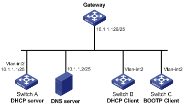
As shown in Figure 29, Switch B (DHCP client) and Switch C (BOOTP client) obtain the static IP address, DNS server address, and gateway address from Switch A (DHCP server).
The client ID of VLAN-interface 2 on Switch B is:
3030-3066-2e65-3234-392e-3830-3530-2d56-6c61-6e2d-696e-7465-7266-6163-6532.
The MAC address of VLAN-interface 2 on Switch C is 000f-e249-8050.
Figure 29: Network diagram
Configuration procedure
Configure the IP address of VLAN-interface 2 on Switch A.
<SwitchA> system-view
[SwitchA] interface vlan-interface 2
[SwitchA-Vlan-interface2] ip address 10.1.1.1 25
[SwitchA-Vlan-interface2] quit
Configure the DHCP server:
# Enable DHCP.
[SwitchA] dhcp enable
# Enable the DHCP server on VLAN-interface 2.
[SwitchA] interface vlan-interface 2
[SwitchA-Vlan-interface2] dhcp select server global-pool
[SwitchA-Vlan-interface2] quit
# Create DHCP address pool 0, configure a static binding, DNS server and gateway in it.
[SwitchA] dhcp server ip-pool 0
[SwitchA-dhcp-pool-0] static-bind ip-address 10.1.1.5 25
[SwitchA-dhcp-pool-0] static-bind client-identifier 3030-3066-2e65-3234-392e-3830-3530-2d56-6c61-6e2d-696e-7465-7266-6163-6532
[SwitchA-dhcp-pool-0] dns-list 10.1.1.2
[SwitchA-dhcp-pool-0] gateway-list 10.1.1.126
[SwitchA-dhcp-pool-0] quit
# Create DHCP address pool 1, configure a static binding, DNS server and gateway in it.
[SwitchA] dhcp server ip-pool 1
[SwitchA-dhcp-pool-1] static-bind ip-address 10.1.1.6 25
[SwitchA-dhcp-pool-1] static-bind mac-address 000f-e249-8050
[SwitchA-dhcp-pool-1] dns-list 10.1.1.2
[SwitchA-dhcp-pool-1] gateway-list 10.1.1.126
Verifying the configuration
After the preceding configuration is complete, Switch B can obtain IP address 10.1.1.5 and other network parameters, and Switch C can obtain IP address 10.1.1.6 and other network parameters from Switch A. You can use the display dhcp server ip-in-use command on the DHCP server to view the IP addresses assigned to the clients.