Configuring an OSPF sham link
Network requirements
As shown in Figure 72, CE 1 and CE 2 belong to VPN 1. Configure an OSPF sham link between PE 1 and PE 2 so traffic between the CEs is forwarded through the MPLS backbone instead of the backdoor link.
Figure 72: Network diagram
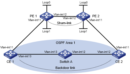
Table 21: Interface and IP address assignment
Device | Interface | IP address | Device | Interface | IP address |
|---|---|---|---|---|---|
CE 1 | Vlan-int11 | 100.1.1.1/24 | CE 2 | Vlan-int11 | 120.1.1.1/24 |
Vlan-int13 | 20.1.1.1/24 | Vlan-int12 | 30.1.1.2/24 | ||
PE 1 | Loop0 | 1.1.1.9/32 | PE 2 | Loop0 | 2.2.2.9/32 |
Loop1 | 3.3.3.3/32 | Loop1 | 5.5.5.5/32 | ||
Vlan-int11 | 100.1.1.2/24 | Vlan-int11 | 120.1.1.2/24 | ||
Vlan-int12 | 10.1.1.1/24 | Vlan-int12 | 10.1.1.2/24 | ||
Switch A | Vlan-int11 | 20.1.1.2/24 | |||
Vlan-int12 | 30.1.1.1/24 |
Configuration procedure
Configure OSPF on the customer networks:
# Configure conventional OSPF on CE 1, Switch A, and CE 2 to advertise subnet addresses of the interfaces (see Table 21). (Details not shown.)
# Set the cost value to 2 for both the link between CE 1 and Switch A, and the link between CE 2 and Switch A. (Details not shown.)
# Execute the display ip routing-table command to verify that CE 1 and CE 2 have learned the route to each other. (Details not shown.)
Configure MPLS L3VPN on the backbone:
# Configure basic MPLS and MPLS LDP on PE 1 to establish LDP LSPs.
<PE1> system-view
[PE1] interface loopback 0
[PE1-LoopBack0] ip address 1.1.1.9 32
[PE1-LoopBack0] quit
[PE1] mpls lsr-id 1.1.1.9
[PE1] mpls ldp
[PE1-ldp] quit
[PE1] interface vlan-interface 12
[PE1-Vlan-interface12] ip address 10.1.1.1 24
[PE1-Vlan-interface12] mpls enable
[PE1-Vlan-interface12] mpls ldp enable
[PE1-Vlan-interface12] quit
# Configure PE 1 to take PE 2 as an MP-IBGP peer.
[PE1] bgp 100
[PE1-bgp-default] peer 2.2.2.9 as-number 100
[PE1-bgp-default] peer 2.2.2.9 connect-interface loopback 0
[PE1-bgp-default] address-family vpnv4
[PE1-bgp-default-vpnv4] peer 2.2.2.9 enable
[PE1-bgp-default-vpnv4] quit
[PE1-bgp-default] quit
# Configure OSPF on PE 1.
[PE1]ospf 1
[PE1-ospf-1]area 0
[PE1-ospf-1-area-0.0.0.0]network 1.1.1.9 0.0.0.0
[PE1-ospf-1-area-0.0.0.0]network 10.1.1.0 0.0.0.255
[PE1-ospf-1-area-0.0.0.0]quit
[PE1-ospf-1]quit
# Configure basic MPLS and MPLS LDP on PE 2 to establish LDP LSPs.
<PE2> system-view
[PE2] interface loopback 0
[PE2-LoopBack0] ip address 2.2.2.9 32
[PE2-LoopBack0] quit
[PE2] mpls lsr-id 2.2.2.9
[PE2] mpls ldp
[PE2-ldp] quit
[PE2] interface vlan-interface 12
[PE2-Vlan-interface12] ip address 10.1.1.2 24
[PE2-Vlan-interface12] mpls enable
[PE2-Vlan-interface12] mpls ldp enable
[PE2-Vlan-interface12] quit
# Configure PE 2 to take PE 1 as an MP-IBGP peer.
[PE2] bgp 100
[PE2-bgp-default] peer 1.1.1.9 as-number 100
[PE2-bgp-default] peer 1.1.1.9 connect-interface loopback 0
[PE2-bgp-default] address-family vpnv4
[PE2-bgp-default-vpnv4] peer 1.1.1.9 enable
[PE2-bgp-default-vpnv4] quit
[PE2-bgp-default] quit
# Configure OSPF on PE 2.
[PE2]ospf 1
[PE2-ospf-1]area 0
[PE2-ospf-1-area-0.0.0.0]network 2.2.2.9 0.0.0.0
[PE2-ospf-1-area-0.0.0.0]network 10.1.1.0 0.0.0.255
[PE2-ospf-1-area-0.0.0.0]quit
[PE2-ospf-1]quit
Configure PEs to allow CE access:
# Configure PE 1.
[PE1] ip vpn-instance vpn1
[PE1-vpn-instance-vpn1] route-distinguisher 100:1
[PE1-vpn-instance-vpn1] vpn-target 1:1
[PE1-vpn-instance-vpn1] quit
[PE1] interface vlan-interface 11
[PE1-Vlan-interface11] ip binding vpn-instance vpn1
[PE1-Vlan-interface11] ip address 100.1.1.2 24
[PE1-Vlan-interface11] quit
[PE1] ospf 100 vpn-instance vpn1
[PE1-ospf-100] domain-id 10
[PE1-ospf-100] area 1
[PE1-ospf-100-area-0.0.0.1] network 100.1.1.0 0.0.0.255
[PE1-ospf-100-area-0.0.0.1] quit
[PE1-ospf-100] quit
[PE2] bgp 100
[PE1-bgp-default] ip vpn-instance vpn1
[PE1-bgp-default-vpn1] address-family ipv4 unicast
[PE1-bgp-default-ipv4-vpn1] import-route ospf 100
[PE1-bgp-default-ipv4-vpn1] import-route direct
[PE1-bgp-default-ipv4-vpn1] quit
[PE1-bgp-default-vpn1] quit
[PE1-bgp-default] quit
# Configure PE 2.
[PE2] ip vpn-instance vpn1
[PE2-vpn-instance-vpn1] route-distinguisher 100:2
[PE2-vpn-instance-vpn1] vpn-target 1:1
[PE2-vpn-instance-vpn1] quit
[PE2] interface vlan-interface 11
[PE2-Vlan-interface11] ip binding vpn-instance vpn1
[PE2-Vlan-interface11] ip address 120.1.1.2 24
[PE2-Vlan-interface11] quit
[PE2] ospf 100 vpn-instance vpn1
[PE2-ospf-100] domain-id 10
[PE2-ospf-100] area 1
[PE2-ospf-100-area-0.0.0.1] network 120.1.1.0 0.0.0.255
[PE2-ospf-100-area-0.0.0.1] quit
[PE2-ospf-100] quit
[PE2] bgp 100
[PE2-bgp-default] ip vpn-instance vpn1
[PE2-bgp-default-vpn1] address-family ipv4 unicast
[PE2-bgp-default-ipv4-vpn1] import-route ospf 100
[PE2-bgp-default-ipv4-vpn1] import-route direct
[PE2-bgp-default-ipv4-vpn1] quit
[PE2-bgp-default-vpn1] quit
[PE2-bgp-default] quit
# Execute the display ip routing-table vpn-instance command on the PEs. Verify that the path to the peer CE is along the OSPF route across the customer networks, instead of the BGP route across the backbone. (Details not shown.)
Configure a sham link:
# Configure PE 1.
[PE1] interface loopback 1
[PE1-LoopBack1] ip binding vpn-instance vpn1
[PE1-LoopBack1] ip address 3.3.3.3 32
[PE1-LoopBack1] quit
[PE1] ospf 100
[PE1-ospf-100] area 1
[PE1-ospf-100-area-0.0.0.1] sham-link 3.3.3.3 5.5.5.5
[PE1-ospf-100-area-0.0.0.1] quit
[PE1-ospf-100] quit
# Configure PE 2.
[PE2] interface loopback 1
[PE2-LoopBack1] ip binding vpn-instance vpn1
[PE2-LoopBack1] ip address 5.5.5.5 32
[PE2-LoopBack1] quit
[PE2] ospf 100
[PE2-ospf-100] area 1
[PE2-ospf-100-area-0.0.0.1] sham-link 5.5.5.5 3.3.3.3
[PE2-ospf-100-area-0.0.0.1] quit
[PE2-ospf-100] quit
Verifying the configuration
# Execute the display ip routing-table vpn-instance command on the PEs to verify the following results (details not shown):
The path to the peer CE is now along the BGP route across the backbone.
A route to the sham link destination address exists.
# Execute the display ip routing-table command on the CEs. Verify that the next hop of the OSPF route to the peer CE is the interface connected to the PE (VLAN interface 11). This means that the VPN traffic to the peer CE is forwarded over the backbone. (Details not shown.)
# Verify that a sham link has been established on PEs, for example, on PE 1.
[PE1] display ospf sham-link

          OSPF Process 100 with Router ID 100.1.1.2
                  Sham link
Area            Neighbor ID     Source IP       Destination IP  State  Cost
 0.0.0.1         120.1.1.2       3.3.3.3         5.5.5.5        P-2-P  1
# Verify that the peer state is Full on PE 1.
[PE1] display ospf sham-link area 1

          OSPF Process 100 with Router ID 100.1.1.2

 Sham link: 3.3.3.3 --> 5.5.5.5
 Neighbor ID: 120.1.1.2        State: Full
 Area: 0.0.0.1
 Cost: 1  State: P-2-P  Type: Sham
 Timers: Hello 10, Dead 40, Retransmit 5, Transmit Delay 1
 Request list: 0  Retransmit list: 0