Auto FRR configuration example
Network requirements
Use RSVP-TE to set up a primary CRLSP that explicitly uses path Switch A—Switch B—Switch C—Switch D.
Configure auto FRR on Switch B to automatically set up bypass tunnels for the primary CRLSP.
Configure BFD for RSVP-TE between Switch B and Switch C. When the link between Switch B and Switch C fails, BFD can detect the failure quickly and notify RSVP-TE of the failure, so RSVP-TE can switch traffic to the bypass tunnel.
Figure 36: Network diagram
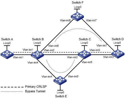
Table 8: Interface and IP address assignment
Device | Interface | IP address | Device | Interface | IP address |
|---|---|---|---|---|---|
Switch A | Loop0 | 1.1.1.1/32 | Switch E | Loop0 | 5.5.5.5/32 |
Vlan-int1 | 2.1.1.1/24 | Vlan-int4 | 3.2.1.2/24 | ||
Switch B | Loop0 | 2.2.2.2/32 | Vlan-int5 | 3.4.1.1/24 | |
Vlan-int1 | 2.1.1.2/24 | Switch C | Loop0 | 3.3.3.3/32 | |
Vlan-int2 | 3.1.1.1/24 | Vlan-int3 | 4.1.1.1/24 | ||
Vlan-int4 | 3.2.1.1/24 | Vlan-int2 | 3.1.1.2/24 | ||
Vlan-int6 | 3.3.1.1/24 | Vlan-int5 | 3.4.1.2/24 | ||
Switch D | Loop0 | 4.4.4.4/32 | Switch F | Loop0 | 6.6.6.6/32 |
Vlan-int3 | 4.1.1.2/24 | Vlan-int6 | 3.3.1.2/24 | ||
Vlan-int7 | 4.2.1.2/24 | Vlan-int7 | 4.2.1.1/24 |
Configuration procedure
Before configuration, disable the spanning tree feature globally or map each VLAN to an MSTI. For more information, see Layer 2—LAN Switching Configuration Guide.
Configure IP addresses and masks for interfaces. (Details not shown.)
Configure IS-IS to advertise interface addresses, including the loopback interface address. (Details not shown.)
Configure an LSR ID, and enable MPLS, MPLS TE, and RSVP-TE on each switch. Enable BFD for RSVP-TE on Switch B and Switch C:
# Configure Switch A.
<SwitchA> system-view
[SwitchA] mpls lsr-id 1.1.1.1
[SwitchA] mpls te
[SwitchA-te] quit
[SwitchA] rsvp
[SwitchA-rsvp] quit
[SwitchA] interface vlan-interface 1
[SwitchA-Vlan-interface1] mpls enable
[SwitchA-Vlan-interface1] mpls te enable
[SwitchA-Vlan-interface1] rsvp enable
[SwitchA-Vlan-interface1] quit
# Configure Switch B.
<SwitchB> system-view
[SwitchB] mpls lsr-id 2.2.2.2
[SwitchB] mpls te
[SwitchB-te] quit
[SwitchB] rsvp
[SwitchB-rsvp] quit
[SwitchB] interface vlan-interface 1
[SwitchB-Vlan-interface1] mpls enable
[SwitchB-Vlan-interface1] mpls te enable
[SwitchB-Vlan-interface1] rsvp enable
[SwitchB-Vlan-interface1] quit
[SwitchB] interface vlan-interface 2
[SwitchB-Vlan-interface2] mpls enable
[SwitchB-Vlan-interface2] mpls te enable
[SwitchB-Vlan-interface2] rsvp enable
[SwitchB-Vlan-interface2] rsvp bfd enable
[SwitchB-Vlan-interface2] quit
[SwitchB] interface vlan-interface 4
[SwitchB-Vlan-interface4] mpls enable
[SwitchB-Vlan-interface4] mpls te enable
[SwitchB-Vlan-interface4] rsvp enable
[SwitchB-Vlan-interface4] quit
[SwitchB] interface vlan-interface 6
[SwitchB-Vlan-interface6] mpls enable
[SwitchB-Vlan-interface6] mpls te enable
[SwitchB-Vlan-interface6] rsvp enable
[SwitchB-Vlan-interface6] quit
# Configure Switch C in the same way that Switch B is configured. Configure Switch D, Switch E, and Switch F in the same way that Switch A is configured. (Details not shown.)
Configure an MPLS TE tunnel on Switch A, the ingress node of the primary CRLSP:
# Configure an explicit path named pri-path for the primary CRLSP.
[SwitchA] explicit-path pri-path
[SwitchA-explicit-path-pri-path] nexthop 2.1.1.2
[SwitchA-explicit-path-pri-path] nexthop 3.1.1.2
[SwitchA-explicit-path-pri-path] nexthop 4.1.1.2
[SwitchA-explicit-path-pri-path] nexthop 4.4.4.4
[SwitchA-explicit-path-pri-path] quit
# Configure an MPLS TE tunnel.
[SwitchA] interface tunnel 1 mode mpls-te
[SwitchA-Tunnel1] ip address 10.1.1.1 255.255.255.0
# Specify the tunnel destination address as the LSR ID of Switch D.
[SwitchA-Tunnel1] destination 4.4.4.4
# Specify the tunnel signaling protocol as RSVP-TE.
[SwitchA-Tunnel1] mpls te signaling rsvp-te
# Specify the explicit path as pri-path.
[SwitchA-Tunnel1] mpls te path preference 1 explicit-path pri-path
# Enable FRR for the MPLS TE tunnel.
[SwitchA-Tunnel1] mpls te fast-reroute
[SwitchA-Tunnel1] quit
# Verify that the MPLS TE interface Tunnel1 is up on Switch A.
[SwitchA] display interface tunnel
Tunnel1
Current state: UP
Line protocol state: UP
Description: Tunnel1 Interface
Bandwidth: 64kbps
Maximum transmission unit: 1496
Internet address: 10.1.1.1/24 (primary)
Tunnel source unknown, destination 4.4.4.4
Tunnel TTL 255
Tunnel protocol/transport CR_LSP
Last clearing of counters: Never
Last 300 seconds input rate: 0 bytes/sec, 0 bits/sec, 0 packets/sec
Last 300 seconds output rate: 1911 bytes/sec, 15288 bits/sec, 0 packets/sec
Input: 0 packets input, 0 bytes, 0 drops
Output: 1526 packets output, 22356852 bytes, 0 drops
# Display detailed information about the MPLS TE tunnel interface on Switch A.
[SwitchA] display mpls te tunnel-interface
Tunnel Name            : Tunnel 1
Tunnel State           : Up (Main CRLSP up, Shared-resource CRLSP down)
Tunnel Attributes      :
  LSP ID               : 16802           Tunnel ID            : 1
  Admin State          : Normal
  Ingress LSR ID       : 2.2.2.2         Egress LSR ID        : 4.4.4.4
  Signaling            : RSVP-TE         Static CRLSP Name    : -
  Resv Style           : SE
  Tunnel mode          : -
  Reverse-LSP name     : -
  Reverse-LSP LSR ID   : -               Reverse-LSP Tunnel ID: -
  Class Type           : CT0             Tunnel Bandwidth     : 0 kbps
  Reserved Bandwidth   : 0 kbps
  Setup Priority       : 7               Holding Priority     : 7
  Affinity Attr/Mask   : 0/0
  Explicit Path        : exp1
  Backup Explicit Path : -
  Metric Type          : TE
  Record Route         : Enabled         Record Label         : Enabled
  FRR Flag             : Enabled         Bandwidth Protection : Disabled
  Backup Bandwidth Flag: Disabled        Backup Bandwidth Type: -
  Backup Bandwidth     : -
  Bypass Tunnel        : No              Auto Created         : No
  Route Pinning        : Disabled
  Retry Limit          : 3               Retry Interval       : 2 sec
  Reoptimization       : Disabled        Reoptimization Freq  : -
  Backup Type          : None            Backup LSP ID        : -
  Auto Bandwidth       : Disabled        Auto Bandwidth Freq  : -
  Min Bandwidth        : -               Max Bandwidth        : -
  Collected Bandwidth  : -
Configure auto FRR on Switch B (the PLR):
# Enable the automatic bypass tunnel setup feature globally.
[SwitchB] mpls te
[SwitchB-te] auto-tunnel backup
# Specify interface numbers 50 to 100 for the automatically created bypass tunnels.
[SwitchB-te-auto-bk] tunnel-number min 50 max 100
[SwitchB-te-auto-bk] quit
Verifying the configuration
# Verify that two tunnels have been created automatically on Switch B.
[SwitchB] display interface tunnel brief
Brief information on interfaces in route mode:
Link: ADM - administratively down; Stby - standby
Protocol: (s) - spoofing
Interface            Link Protocol Primary IP      Description
Tun50                UP   DOWN     --
Tun51                UP   DOWN     --
# Display information about Tunnel 50 and Tunnel 51 on Switch B. The output shows that Tunnel 50 and Tunnel 51 are automatically created bypass tunnels. Tunnel 50 is a node-protection bypass tunnel (egress LSR ID is 4.4.4.4, the LSR ID of Switch D). Tunnel 51 is a link-protection bypass tunnel (egress LSR ID is 3.3.3.3, the LSR ID of Switch C).
[SwitchB] display mpls te tunnel-interface tunnel 50
Tunnel Name            : Tunnel 50
Tunnel State           : Up (Main CRLSP up, Shared-resource CRLSP down)
Tunnel Attributes      :
  LSP ID               : 16802           Tunnel ID            : 50
  Admin State          : Normal
  Ingress LSR ID       : 2.2.2.2         Egress LSR ID        : 4.4.4.4
  Signaling            : RSVP-TE         Static CRLSP Name    : -
  Resv Style           : SE
  Tunnel mode          : -
  Reverse-LSP name     : -
  Reverse-LSP LSR ID   : -               Reverse-LSP Tunnel ID: -
  Class Type           : CT0             Tunnel Bandwidth     : 0 kbps
  Reserved Bandwidth   : 0 kbps
  Setup Priority       : 7               Holding Priority     : 7
  Affinity Attr/Mask   : 0/0
  Explicit Path        : -
  Backup Explicit Path : -
  Metric Type          : TE
  Record Route         : Enabled         Record Label         : Disabled
  FRR Flag             : Disabled        Bandwidth Protection : Disabled
  Backup Bandwidth Flag: Disabled        Backup Bandwidth Type: -
  Backup Bandwidth     : -
  Bypass Tunnel        : Yes             Auto Created         : Yes
  Route Pinning        : Disabled
  Retry Limit          : 3               Retry Interval       : 2 sec
  Reoptimization       : Disabled        Reoptimization Freq  : -
  Backup Type          : None            Backup LSP ID        : -
  Auto Bandwidth       : Disabled        Auto Bandwidth Freq  : -
  Min Bandwidth        : -               Max Bandwidth        : -
  Collected Bandwidth  : -
[SwitchB] display mpls te tunnel-interface tunnel 51
Tunnel Name            : Tunnel 51
Tunnel State           : Up (Main CRLSP up, Shared-resource CRLSP down)
Tunnel Attributes      :
  LSP ID               : 16802           Tunnel ID            : 51
  Admin State          : Normal
  Ingress LSR ID       : 2.2.2.2         Egress LSR ID        : 3.3.3.3
  Signaling            : RSVP-TE         Static CRLSP Name    : -
  Resv Style           : SE
  Tunnel mode          : -
  Reverse-LSP name     : -
  Reverse-LSP LSR ID   : -               Reverse-LSP Tunnel ID: -
  Class Type           : CT0             Tunnel Bandwidth     : 0 kbps
  Reserved Bandwidth   : 0 kbps
  Setup Priority       : 7               Holding Priority     : 7
  Affinity Attr/Mask   : 0/0
  Explicit Path        : -
  Backup Explicit Path : -
  Metric Type          : TE
  Record Route         : Enabled         Record Label         : Disabled
  FRR Flag             : Disabled        Bandwidth Protection : Disabled
  Backup Bandwidth Flag: Disabled        Backup Bandwidth Type: -
  Backup Bandwidth     : -
  Bypass Tunnel        : Yes             Auto Created         : Yes
  Route Pinning        : Disabled
  Retry Limit          : 3               Retry Interval       : 2 sec
  Reoptimization       : Disabled        Reoptimization Freq  : -
  Backup Type          : None            Backup LSP ID        : -
  Auto Bandwidth       : Disabled        Auto Bandwidth Freq  : -
  Min Bandwidth        : -               Max Bandwidth        : -
  Collected Bandwidth  : -
# Verify that the current bypass tunnel that protects the primary CRLSP is tunnel 50.
[SwitchB] display mpls lsp
FEC                         Proto    In/Out Label    Interface/Out NHLFE
2.2.2.2/51/16802            RSVP     -/3             Vlan4
2.2.2.2/1/16802             RSVP     -/1151          Vlan2
Backup                               -/3             Tun50
2.2.2.2/50/16802            RSVP     -/3             Vlan6
3.2.1.2                     Local    -/-             Vlan6
3.3.1.2                     Local    -/-             Vlan6
# Display detailed information about MPLS TE Tunnel1 (the tunnel for the primary CRLSP) on Switch A. The output shows that Tunnel1 is protected by the bypass tunnel Tunnel50, and the protected node is 3.1.1.1.
[SwitchA] display rsvp lsp tunnel-id 1 verbose
Tunnel name: Tunnel1
Destination: 4.4.4.4                      Source: 1.1.1.1
Tunnel ID: 1                              LSP ID: 16802
LSR type: Ingress                         Direction: Unidirectional
Setup priority: 7                         Holding priority: 7
In-Label: -                               Out-Label: 1150
In-Interface: -                           Out-Interface: Vlan1
Nexthop: 2.1.1.2                          Exclude-any: 0
Include-Any: 0                            Include-all: 0
Average bitrate: 0 kbps                   Maximum burst: 1000.00 bytes
Path MTU: 1500                            Class type: CT0
RRO number: 12
  2.1.1.1/32         Flag: 0x00 (No FRR)
  2.1.1.2/32         Flag: 0x00 (No FRR)
  1150               Flag: 0x01 (Global label)
  2.2.2.2/32         Flag: 0x20 (No FRR/Node-ID)
  3.1.1.1/32         Flag: 0x09 (FRR Avail/Node-Prot)
  3.1.1.2/32         Flag: 0x00 (No FRR)
  1151               Flag: 0x01 (Global label)
  3.3.3.3/32         Flag: 0x20 (No FRR/Node-ID)
  4.1.1.1/32         Flag: 0x00 (No FRR)
  4.1.1.2/32         Flag: 0x00 (No FRR)
  3                  Flag: 0x01 (Global label)
  4.4.4.4/32         Flag: 0x20 (No FRR/Node-ID)
Fast Reroute protection: Ready
  FRR inner label: 3           Bypass tunnel: Tunnel50