Manual bypass tunnel for FRR configuration example
Network requirements
On the primary CRLSP Switch A—Switch B—Switch C—Switch D, use FRR to protect the link Switch B—Switch C.
Use RSVP-TE to establish the primary CRLSP and bypass tunnel based on the constraints of the explicit paths to transmit data between the two IP networks. The bypass tunnel uses path Switch B—Switch E—Switch C. Switch B is the PLR and Switch C is the MP.
Configure BFD for RSVP-TE between Switch B and Switch C. When the link between Switch B and Switch C fails, BFD can detect the failure quickly and notify RSVP-TE of the failure, so RSVP-TE can switch traffic to the bypass tunnel.
Figure 35: Network diagram
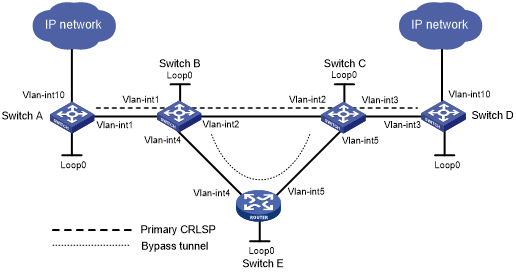
Table 7: Interface and IP address assignment
Device | Interface | IP address | Device | Interface | IP address |
|---|---|---|---|---|---|
Switch A | Loop0 | 1.1.1.1/32 | Switch B | Loop0 | 2.2.2.2/32 |
Vlan-int1 | 2.1.1.1/24 | Vlan-int1 | 2.1.1.2/24 | ||
Vlan-int10 | 100.1.1.1/24 | Vlan-int2 | 3.1.1.1/24 | ||
Switch D | Loop0 | 4.4.4.4/32 | Vlan-int4 | 3.2.1.1/24 | |
Vlan-int3 | 4.1.1.2/24 | Switch C | Loop0 | 3.3.3.3/32 | |
Vlan-int10 | 100.1.1.1/24 | Vlan-int3 | 4.1.1.1/24 | ||
Switch E | Loop0 | 5.5.5.5/32 | Vlan-int2 | 3.1.1.2/24 | |
Vlan-int4 | 3.2.1.2/24 | Vlan-int5 | 3.3.1.2/24 | ||
Vlan-int5 | 3.3.1.1/24 |
Configuration procedure
Configure IP addresses and masks for interfaces. (Details not shown.)
Configure IS-IS to advertise interface addresses, including the loopback interface address. (Details not shown.)
Configure an LSR ID, and enable MPLS, MPLS TE, and RSVP-TE on each switch. Enable BFD for RSVP-TE on Switch B and Switch C:
# Configure Switch A.
<SwitchA> system-view
[SwitchA] mpls lsr-id 1.1.1.1
[SwitchA] mpls te
[SwitchA-te] quit
[SwitchA] rsvp
[SwitchA-rsvp] quit
[SwitchA] interface vlan-interface 1
[SwitchA-Vlan-interface1] mpls enable
[SwitchA-Vlan-interface1] mpls te enable
[SwitchA-Vlan-interface1] rsvp enable
[SwitchA-Vlan-interface1] quit
# Configure Switch B.
<SwitchB> system-view
[SwitchB] mpls lsr-id 2.2.2.2
[SwitchB] mpls te
[SwitchB-te] quit
[SwitchB] rsvp
[SwitchB-rsvp] quit
[SwitchB] interface vlan-interface 1
[SwitchB-Vlan-interface1] mpls enable
[SwitchB-Vlan-interface1] mpls te enable
[SwitchB-Vlan-interface1] rsvp enable
[SwitchB-Vlan-interface1] quit
[SwitchB] interface vlan-interface 2
[SwitchB-Vlan-interface2] mpls enable
[SwitchB-Vlan-interface2] mpls te enable
[SwitchB-Vlan-interface2] rsvp enable
[SwitchB-Vlan-interface2] rsvp bfd enable
[SwitchB-Vlan-interface2] quit
[SwitchB] interface vlan-interface 4
[SwitchB-Vlan-interface4] mpls enable
[SwitchB-Vlan-interface4] mpls te enable
[SwitchB-Vlan-interface4] rsvp enable
[SwitchB-Vlan-interface4] quit
# Configure Switch C in the same way that Switch B is configured. Configure Switch D and Switch E in the same way that Switch A is configured. (Details not shown.)
Configure an MPLS TE tunnel on Switch A, the ingress node of the primary CRLSP:
# Configure an explicit path for the primary CRLSP.
[SwitchA] explicit-path pri-path
[SwitchA-explicit-path-pri-path] nexthop 2.1.1.2
[SwitchA-explicit-path-pri-path] nexthop 3.1.1.2
[SwitchA-explicit-path-pri-path] nexthop 4.1.1.2
[SwitchA-explicit-path-pri-path] nexthop 4.4.4.4
[SwitchA-explicit-path-pri-path] quit
# Create MPLS TE tunnel interface Tunnel 4 for the primary CRLSP.
[SwitchA] interface tunnel 4 mode mpls-te
[SwitchA-Tunnel4] ip address 10.1.1.1 255.255.255.0
# Specify the tunnel destination address as the LSR ID of Switch D.
[SwitchA-Tunnel4] destination 4.4.4.4
# Specify the tunnel signaling protocol as RSVP-TE.
[SwitchA-Tunnel4] mpls te signaling rsvp-te
# Specify the explicit path to be used as pri-path.
[SwitchA-Tunnel4] mpls te path preference 1 explicit-path pri-path
# Enable FRR for the MPLS TE tunnel.
[SwitchA-Tunnel4] mpls te fast-reroute
[SwitchA-Tunnel4] quit
# Verify that the tunnel interface Tunnel 4 is up on Switch A.
[SwitchA] display interface tunnel
Tunnel4
Current state: UP
Line protocol current state: UP
Description: Tunnel4 Interface
Bandwidth: 64kbps
Maximum transmission unit: 1496
Internet address: 9.1.1.1/24 (primary)
Tunnel source unknown, destination 4.4.4.4
Tunnel TTL 255
Tunnel protocol/transport CR_LSP
Last clearing of counters: Never
Last 300 seconds input rate: 0 bytes/sec, 0 bits/sec, 0 packets/sec
Last 300 seconds output rate: 1911 bytes/sec, 15288 bits/sec, 0 packets/sec
Input: 0 packets input, 0 bytes, 0 drops
Output: 1526 packets output, 22356852 bytes, 0 drops
# Display detailed information about the MPLS TE tunnel on Switch A.
[SwitchA] display mpls te tunnel-interface
Tunnel Name            : Tunnel 4
Tunnel State           : Up (Main CRLSP up, Shared-resource CRLSP down)
Tunnel Attributes      :
  LSP ID               : 48960           Tunnel ID            : 4
  Admin State          : Normal
  Ingress LSR ID       : 1.1.1.1         Egress LSR ID        : 3.3.3.3
  Signaling            : RSVP-TE         Static CRLSP Name    : -
  Resv Style           : SE
  Tunnel mode          : -
  Reverse-LSP name     : -
  Reverse-LSP LSR ID   : -               Reverse-LSP Tunnel ID: -
  Class Type           : CT0             Tunnel Bandwidth     : 0 kbps
  Reserved Bandwidth   : 0 kbps
  Setup Priority       : 7               Holding Priority     : 7
  Affinity Attr/Mask   : 0/0
  Explicit Path        : pri-path
  Backup Explicit Path : -
  Metric Type          : TE
  Record Route         : Enabled         Record Label         : Enabled
  FRR Flag             : Enabled         Bandwidth Protection : Disabled
  Backup Bandwidth Flag: Disabled        Backup Bandwidth Type: -
  Backup Bandwidth     : -
  Bypass Tunnel        : No              Auto Created         : No
  Route Pinning        : Disabled
  Retry Limit          : 10              Retry Interval       : 2 sec
  Reoptimization       : Disabled        Reoptimization Freq  : -
  Backup Type          : None            Backup LSP ID        : -
  Auto Bandwidth       : Disabled        Auto Bandwidth Freq  : -
  Min Bandwidth        : -               Max Bandwidth        : -
  Collected Bandwidth  : -
Configure a bypass tunnel on Switch B (the PLR):
# Configure an explicit path for the bypass tunnel.
[SwitchB] explicit-path by-path
[SwitchB-explicit-path-by-path] nexthop 3.2.1.2
[SwitchB-explicit-path-by-path] nexthop 3.3.1.2
[SwitchB-explicit-path-by-path] nexthop 3.3.3.3
[SwitchB-explicit-path-by-path] quit
# Create MPLS TE tunnel interface Tunnel 5 for the bypass tunnel.
[SwitchB] interface tunnel 5 mode mpls-te
[SwitchB-Tunnel5] ip address 11.1.1.1 255.255.255.0
# Specify the tunnel destination address as LSR ID of Switch C.
[SwitchB-Tunnel5] destination 3.3.3.3
# Specify the tunnel signaling protocol as RSVP-TE.
[SwitchB-Tunnel5] mpls te signaling rsvp-te
# Specify the explicit path to be used as by-path.
[SwitchB-Tunnel5] mpls te path preference 1 explicit-path by-path
# Set the bandwidth that the bypass tunnel can protect.
[SwitchB-Tunnel5] mpls te backup bandwidth un-limited
[SwitchB-Tunnel5] quit
# Bind the bypass tunnel to the protected interface.
[SwitchB] interface vlan-interface 2
[SwitchB-Vlan-interface2] mpls te fast-reroute bypass-tunnel tunnel 5
[SwitchB-Vlan-interface2] quit
# Execute the display interface tunnel command on Switch B to verify that the tunnel interface Tunnel 5 is up. (Details not shown.)
Configure a static route on Switch A to direct the traffic destined for subnet 100.1.2.0/24 to MPLS TE tunnel 4.
[SwitchA] ip route-static 100.1.2.0 24 tunnel 4 preference 1
Verifying the configuration
# Display LSP entries on each switch to verify that Switch B and Switch C each have two CRLSPs and the bypass tunnel backs up the primary CRLSP.
[SwitchA] display mpls lsp
FEC                         Proto    In/Out Label    Interface/Out NHLFE
1.1.1.1/4/61400             RSVP     -/1245          Vlan1
2.1.1.2                     Local    -/-             Vlan1
[SwitchB] display mpls lsp
FEC                         Proto    In/Out Label    Interface/Out NHLFE
1.1.1.1/4/614000            RSVP     1245/3          Vlan2
Backup                               1245/3          Tun5
2.2.2.2/5/30914             RSVP     -/1150          Vlan2
3.2.1.2                     Local    -/-             Vlan4
3.1.1.2                     Local    -/-             Vlan2
[SwitchE] display mpls lsp
FEC                         Proto    In/Out Label    Interface/Out NHLFE
2.2.2.2/5/30914             RSVP     1150/3          Vlan5
3.3.1.2                     Local    -/-             Vlan5
# Shut down the protected interface VLAN-interface 2 on the PLR (Switch B).
[SwitchB] interface vlan-interface 2
[SwitchB-Vlan-interface2] shutdown
[SwitchB-Vlan-interface2] quit
# Execute the display interface tunnel 4 command on Switch A to display information about the primary CRLSP. The output shows that the tunnel interface is still up. (Details not shown.)
# Display detailed information about the tunnel interface on Switch A.
[SwitchA] display mpls te tunnel-interface
Tunnel Name            : Tunnel 4
Tunnel State           : Up (Main CRLSP up, Shared-resource CRLSP being set up)
Tunnel Attributes      :
  LSP ID               : 18753           Tunnel ID            : 4
  Admin State          : Normal
  Ingress LSR ID       : 1.1.1.1         Egress LSR ID        : 3.3.3.3
  Signaling            : RSVP-TE         Static CRLSP Name    : -
  Resv Style           : SE
  Tunnel mode          : -
  Reverse-LSP name     : -
  Reverse-LSP LSR ID   : -               Reverse-LSP Tunnel ID: -
  Class Type           : CT0             Tunnel Bandwidth     : 0 kbps
  Reserved Bandwidth   : 0 kbps
  Setup Priority       : 7               Holding Priority     : 7
  Affinity Attr/Mask   : 0/0
  Explicit Path        : pri-path
  Backup Explicit Path : -
  Metric Type          : TE
  Record Route         : Enabled         Record Label         : Enabled
  FRR Flag             : Enabled         Bandwidth Protection : Disabled
  Backup Bandwidth Flag: Disabled        Backup Bandwidth Type: -
  Backup Bandwidth     : -
  Bypass Tunnel        : No              Auto Created         : No
  Route Pinning        : Disabled
  Retry Limit          : 10              Retry Interval       : 2 sec
  Reoptimization       : Disabled        Reoptimization Freq  : -
  Backup Type          : None            Backup LSP ID        : -
  Auto Bandwidth       : Disabled        Auto Bandwidth Freq  : -
  Min Bandwidth        : -               Max Bandwidth        : -
  Collected Bandwidth  : -
![[NOTE: ]](images/note.png) | NOTE: If you execute the display mpls te tunnel-interface command immediately after an FRR, you can see two CRLSPs in up state. This is because FRR uses the make-before-break mechanism to set up a new LSP, and the old LSP is deleted after the new one has been established for a while. | |
# Verify that the bypass tunnel is in use on Switch B.
[SwitchB] display mpls lsp
FEC                         Proto    In/Out Label    Interface/Out NHLFE
1.1.1.1/4/61400             RSVP     1136/3          Tun5
2.2.2.2/5/30914             RSVP     -/1149          Vlan4
3.2.1.2                     Local    -/-             Vlan4
# On the PLR, configure the interval for selecting an optimal bypass tunnel as 5 seconds.
[SwitchB] mpls te
[SwitchB-te] fast-reroute timer 5
[SwitchB-te] quit
# On the PLR, bring up the protected interface VLAN-interface 2.
[SwitchB] interface vlan-interface 2
[SwitchB-Vlan-interface2] undo shutdown
# Execute the display interface tunnel 4 command on Switch A to display information about the primary CRLSP. The output shows that the tunnel interface is in up state. (Details not shown.)
# Wait for about 5 seconds, execute the display mpls lsp verbose command on Switch B. The output shows that Tunnel 5 is bound to interface VLAN-interface 2 but not in use. (Details not shown.)
# Execute the display ip routing-table command on Switch A. The output shows a static route entry with interface Tunnel 4 as the output interface. (Details not shown.)