Main mode IKE with pre-shared key authentication configuration example
Network requirements
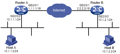
As shown in Figure 141, configure an IKE-based IPsec tunnel between Device A and Deice B to secure the communication between subnet 10.1.1.0/24 and subnet 10.1.2.0/24.
Configure Device A and Device B to use the default IKE proposal for the IKE negotiation to set up the IPsec SAs.
Configure the two devices to use the pre-shared key authentication method for the IKE negotiation phase 1.
Figure 136: Network diagram
Configuration procedure
Configure Device A:
# Assign an IP address to each interface. (Details not shown.)
# Configure IPv4 advanced ACL 3101 to identify traffic from subnet 10.1.1.0/24 to subnet 10.1.2.0/24.
<DeviceA> system-view
[DeviceA] acl advanced 3101
[DeviceA-acl-ipv4-adv-3101] rule permit ip source 10.1.1.0 0.0.0.255 destination 10.1.2.0 0.0.0.255
[DeviceA-acl-ipv4-adv-3101] quit
# Create an IPsec transform set named tran1.
[DeviceA] ipsec transform-set tran1
# Set the packet encapsulation mode to tunnel.
[DeviceA-ipsec-transform-set-tran1] encapsulation-mode tunnel
# Use the ESP protocol for the IPsec transform set.
[DeviceA-ipsec-transform-set-tran1] protocol esp
# Specify the encryption and authentication algorithms.
[DeviceA-ipsec-transform-set-tran1] esp encryption-algorithm aes-cbc-128
[DeviceA-ipsec-transform-set-tran1] esp authentication-algorithm sha1
[DeviceA-ipsec-transform-set-tran1] quit
# Create an IKE keychain named keychain1.
[DeviceA] ike keychain keychain1
# Specify 123456TESTplat&! in plain text as the pre-shared key to be used with the remote peer at 2.2.2.2.
[DeviceA-ike-keychain-keychain1] pre-shared-key address 2.2.2.2 255.255.0.0 key simple 123456TESTplat&!
[DeviceA-ike-keychain-keychain1] quit
# Create an IKE profile named profile1.
[DeviceA] ike profile profile1
# Specify IKE keychain keychain1.
[DeviceA-ike-profile-profile1] keychain keychain1
# Configure the local ID with the identity type as IP address and the value as 1.1.1.1.
[DeviceA-ike-profile-profile1] local-identity address 1.1.1.1
# Configure a peer ID with the identity type as IP address and the value as 2.2.2.2/16.
[DeviceA-ike-profile-profile1] match remote identity address 2.2.2.2 255.255.0.0
[DeviceA-ike-profile-profile1] quit
# Create an IKE-based IPsec policy entry. Specify the policy name as map1 and set the sequence number to 10.
[DeviceA] ipsec policy map1 10 isakmp
# Specify the remote IP address 2.2.2.2 for the IPsec tunnel.
[DeviceA-ipsec-policy-isakmp-map1-10] remote-address 2.2.2.2
# Specify ACL 3101 to identify the traffic to be protected.
[DeviceA-ipsec-policy-isakmp-map1-10] security acl 3101
# Specify the IPsec transform set tran1 for the IPsec policy.
[DeviceA-ipsec-policy-isakmp-map1-10] transform-set tran1
# Specify IKE profile profile1 for the IPsec policy.
[DeviceA-ipsec-policy-isakmp-map1-10] ike-profile profile1
[DeviceA-ipsec-policy-isakmp-map1-10] quit
# Apply IPsec policy map1 to interface GigabitEthernet 2/0/1.
[DeviceA] interface gigabitethernet 2/0/1
[DeviceA-GigabitEthernet2/0/1] ipsec apply policy map1
[DeviceA-GigabitEthernet2/0/1] quit
# Configure a static route to the subnet where Host B resides. The command uses the direct next hop address (1.1.1.2) as an example.
[DeviceA] ip route-static 10.1.2.0 255.255.255.0 1.1.1.2
Configure Device B:
# Assign an IP address to each interface. (Details not shown.)
# Configure IPv4 advanced ACL 3101 to identify traffic from subnet 10.1.2.0/24 to subnet 10.1.1.0/24.
<DeviceB> system-view
[DeviceB] acl advanced 3101
[DeviceB-acl-ipv4-adv-3101] rule permit ip source 10.1.2.0 0.0.0.255 destination 10.1.1.0 0.0.0.255
[DeviceB-acl-ipv4-adv-3101] quit
# Create an IPsec transform set named tran1.
[DeviceB] ipsec transform-set tran1
# Set the packet encapsulation mode to tunnel.
[DeviceB-ipsec-transform-set-tran1] encapsulation-mode tunnel
# Use the ESP protocol for the IPsec transform set.
[DeviceB-ipsec-transform-set-tran1] protocol esp
# Specify the encryption and authentication algorithms.
[DeviceB-ipsec-transform-set-tran1] esp encryption-algorithm aes-cbc-128
[DeviceB-ipsec-transform-set-tran1] esp authentication-algorithm sha1
[DeviceB-ipsec-transform-set-tran1] quit
# Create an IKE keychain named keychain1.
[DeviceB]ike keychain keychain1
# Specify 123456TESTplat&! in plain text as the pre-shared key to be used with the remote peer at 1.1.1.1.
[DeviceB-ike-keychain-keychain1] pre-shared-key address 1.1.1.1 255.255.0.0 key simple 123456TESTplat&!
[DeviceB-ike-keychain-keychain1] quit
# Create an IKE profile named profile1.
[DeviceB] ike profile profile1
# Specify IKE keychain keychain1
[DeviceB-ike-profile-profile1] keychain keychain1
# Configure the local ID with the identity type as IP address and the value as 2.2.2.2.
[DeviceB-ike-profile-profile1] local-identity address 2.2.2.2
# Configure a peer ID with the identity type as IP address and the value as 1.1.1.1/16.
[DeviceB-ike-profile-profile1] match remote identity address 1.1.1.1 255.255.0.0
[DeviceB-ike-profile-profile1] quit
# Create an IKE-based IPsec policy entry. Specify the policy name as use1 and set the sequence number to 10.
[DeviceB] ipsec policy use1 10 isakmp
# Specify the remote IP address 1.1.1.1 for the IPsec tunnel.
[DeviceB-ipsec-policy-isakmp-use1-10] remote-address 1.1.1.1
# Specify ACL 3101 to identify the traffic to be protected.
[DeviceB-ipsec-policy-isakmp-use1-10] security acl 3101
# Specify the IPsec transform set tran1 for the IPsec policy.
[DeviceB-ipsec-policy-isakmp-use1-10] transform-set tran1
# Specify IKE profile profile1 for the IPsec policy.
[DeviceB-ipsec-policy-isakmp-use1-10] ike-profile profile1
[DeviceB-ipsec-policy-isakmp-use1-10] quit
# Apply IPsec policy use1 to interface GigabitEthernet 2/0/1.
[DeviceB] interface gigabitethernet 2/0/1
[DeviceB-GigabitEthernet2/0/1] ipsec apply policy use1
# Configure a static route to the subnet where Host A resides. The command uses the direct next hop address (2.2.2.1) as an example.
[DeviceB] ip route-static 10.1.1.0 255.255.255.0 2.2.2.1
Verifying the configuration
# Initiate a connection from subnet 10.1.1.0/24 to subnet 10.1.2.0/24 to trigger IKE negotiation. After IPsec SAs are successfully negotiated by IKE, traffic between the two subnets is IPsec protected.
# Display the IKE proposal configuration on Device A and Device B. Because no IKE proposal is configured, the command displays the default IKE proposal.
[DeviceA] display ike proposal
 Priority Authentication Authentication Encryption  Diffie-Hellman Duration
              method       algorithm    algorithm       group      (seconds)
----------------------------------------------------------------------------
default  PRE-SHARED-KEY     SHA1       AES-CBC-128     Group 1        86400

[DeviceB] display ike proposal
 Priority Authentication Authentication Encryption  Diffie-Hellman Duration
              method       algorithm    algorithm       group      (seconds)
----------------------------------------------------------------------------
default  PRE-SHARED-KEY     SHA1       AES-CBC-128     Group 1        86400
# Display the IKE SA on Device A.
[DeviceA] display ike sa
    Connection-ID   Remote                Flag         DOI
------------------------------------------------------------------
    1               2.2.2.2               RD           IPSEC
Flags:
RD--READY RL--REPLACED FD-FADING
# Display the IPsec SAs generated on Device A.
[DeviceA] display ipsec sa
-------------------------------
Interface: GigabitEthernet2/0/1
-------------------------------

  -----------------------------
  IPsec policy: map1
  Sequence number: 10
  Mode: ISAKMP
  Flow table status: Active
  -----------------------------
    Tunnel id: 0
    Encapsulation mode: tunnel
    Perfect forward secrecy:
    Inside VRF:
    Extended Sequence Number enable: N
    Traffic Flow Confidentiality enable: N
    Path MTU: 1456
    Tunnel:
        local  address: 1.1.1.1
        remote address: 2.2.2.2
    Flow:
    sour addr: 10.1.1.0/255.255.255.0  port: 0  protocol: ip
    dest addr: 10.1.2.0/255.255.255.0  port: 0  protocol: ip

    [Inbound ESP SAs]
      SPI: 3264152513 (0xc28f03c1)
      Connection ID: 1
      Transform set: ESP-ENCRYPT-AES-CBC-128 ESP-AUTH-SHA1
      SA duration (kilobytes/sec): 1843200/3600
      SA remaining duration (kilobytes/sec): 1843200/3484
      Max received sequence-number:
      Anti-replay check enable: Y
      Anti-replay window size: 64
      UDP encapsulation used for NAT traversal: N
      Status: Active

    [Outbound ESP SAs]
      SPI: 738451674 (0x2c03e0da)
      Connection ID: 2
      Transform set: ESP-ENCRYPT-AES-CBC-128 ESP-AUTH-SHA1
      SA duration (kilobytes/sec): 1843200/3600
      SA remaining duration (kilobytes/sec): 1843200/3484
      Max received sequence-number:
      UDP encapsulation used for NAT traversal: N
      Status: Active
# Display the IKE SA and IPsec SAs on Device B.
[DeviceB] display ike sa
[DeviceB] display ipsec sa