Setup overview
Before you begin
-
For important safety, environmental, and regulatory information, see the Safety and Compliance Information for Server, Storage, Power, Networking, and Rack Products on the Hewlett Packard Enterprise website.
-
Select an installation site that meets the detailed installation site requirements described in the server user guide.
-
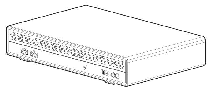
Unpack the server shipping carton, and locate the materials and documentation necessary for installing the server.
For more pre-installation information, see the HPE ProLiant Thin Micro TM200 Server User Guide.
Component identification
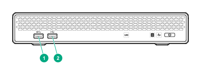
Front panel components
Front panel LEDs and button
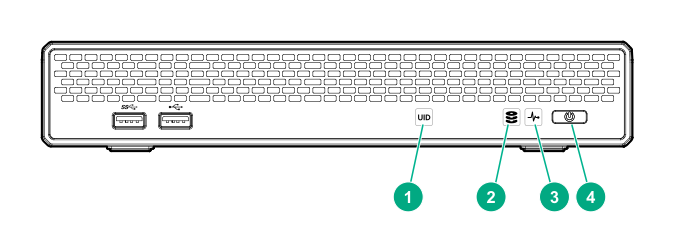
When all LEDs described in this table flash simultaneously, a power fault has occurred. For more information, see the "Front panel LED power fault codes" section in the HPE ProLiant Thin Micro TM200 Server User Guide.
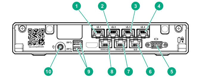
Rear panel components
Rear panel LEDs and button
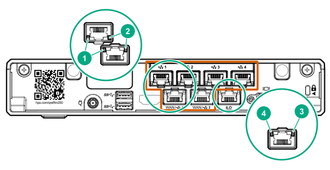
| Item | Description | Status |
|---|---|---|
| 1 | NIC link LED |
Solid green = Link exists Off = No link exists |
| 2 | NIC status LED |
Solid green = Linked to network Flashing green = Network active Off = No network activity |
| 3 | iLO status LED |
Solid green = Linked to network Flashing green = Network active Off = No network activity |
| 4 | iLO link LED |
Green = Network link Off = No network link |
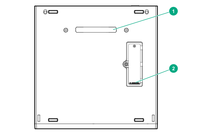
Bottom components
Server warnings and cautions
Installing the server on a mounting/docking hardware option
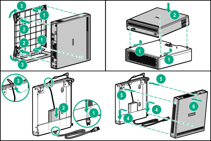
Do not connect the power cord to the power source yet.
For detailed server mounting/docking instructions, see the HPE ProLiant Thin Micro TM200 Server User Guide.
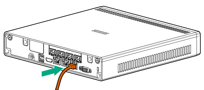
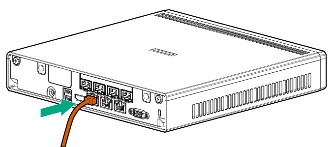
Connecting the network and peripheral cabling
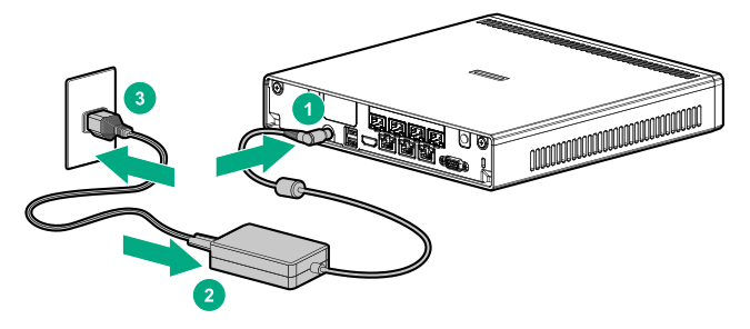
Connecting the power cord and powering on the server
Installing an operating system (OS)
To operate properly, the server must have a supported operating system. For information on supported operating systems, contact your authorized HPE representative.
This server supports Class 3 UEFI implementation. UEFI Class 3 implementation only supports UEFI Boot Mode; there is no support for Legacy BIOS Boot Mode. To prevent errors in installing the operating system, recognizing boot media, and other boot-related errors, observe the relevant UEFI requirements. For more information on these requirements, see Important UEFI Requirements (for HPE ProLiant Thin Micro Servers) on the Hewlett Packard Enterprise website.
To install an operating system on the server, use one of the following methods.
- Manual installation – Insert the operating system disc into a USB-attached DVD-ROM drive (user provided) and reboot the server.
- Remote deployment installation – Use Insight Control server provisioning for an automated solution to remotely deploy an operating system.
For additional system drivers, firmware, and software updates, download the Service Pack for ProLiant from the Hewlett Packard Enterprise website. Update the software and firmware before using the server for the first time, unless any installed software or components require an older version.
For more information on using these installation methods, see the Hewlett Packard Enterprise website.
Registering for HPE remote support
HPE remote support provides automatic submission of hardware events to Hewlett Packard Enterprise to prevent downtime and enable faster issue resolution. You can register directly to Hewlett Packard Enterprise or through an Insight RS Hosting Device. For more information, see the Insight Control documentation on the Hewlett Packard Enterprise website.
Registering the server
To experience quicker service and more efficient support, register the product at the Hewlett Packard Enterprise Product Registration website.
Additional information
Hewlett Packard Enterprise is committed to providing documentation that meets your needs. To help us improve the documentation, send any errors, suggestions, or comments to Documentation Feedback. When submitting your feedback, include the document title, part number, edition, and publication date located on the front cover of the document. For online help content, include the product name, product version, help edition, and publication date located on the legal notices page.