HPE Telco Blueprint network architecture
- Switches configured as part of the blueprint
Management switches (Out of Band Management - HPE FlexFabric 5900)
Data switches (Top of the Rack - HPE StoreFabric SN2100M)
- Additional switch configurations that may be required on the following switches for Telco Blueprint connectivity
Customer infrastructure switch
Border Leaf switches (Customer end Virtual Tunnel End Point (VTEP))
Spine switches (non-VTEP)
NOTE:These switch configurations are optional and depend on the data center setup.
- Management switch
The management switch uses Out-of-Band Management which involves the use of dedicated channel for managing network devices. For more information on the sample Management switch configuration, see Configuring FlexFabric 5900 (Management) switch.
- Data switch
- For this blueprint, the Data switch (HPE StoreFabric SN2100M) has been configured as the Top-of-Rack switch. Data switches support internal API, storage management, and tenant communications in NFVI. These switches are configured in High Availability (HA) mode. For more information on the sample Data switch configuration, see Appendix F: Sample Configuration for Mellanox SN2100 Switches.IMPORTANT:
Each data switch provides five physical uplink ports per switch to the customer network. The maximum and minimum bandwidth per port are 100G and 10G respectively. The count of the uplink ports may vary with the type of data switch used.
- Customer infrastructure switch
The customer infrastructure switch is positioned in the customer data center. The customer infrastructure switch must be configured with iLO-OOBM network (VLAN and IP interfaces) by the network administrator at the customer end to allow the HPE Management switch to communicate. For more information on how to configure the iLO-OOBM VLAN IP addresses, see Configuring iLO-OOBM VLAN in customer infrastructure switch.
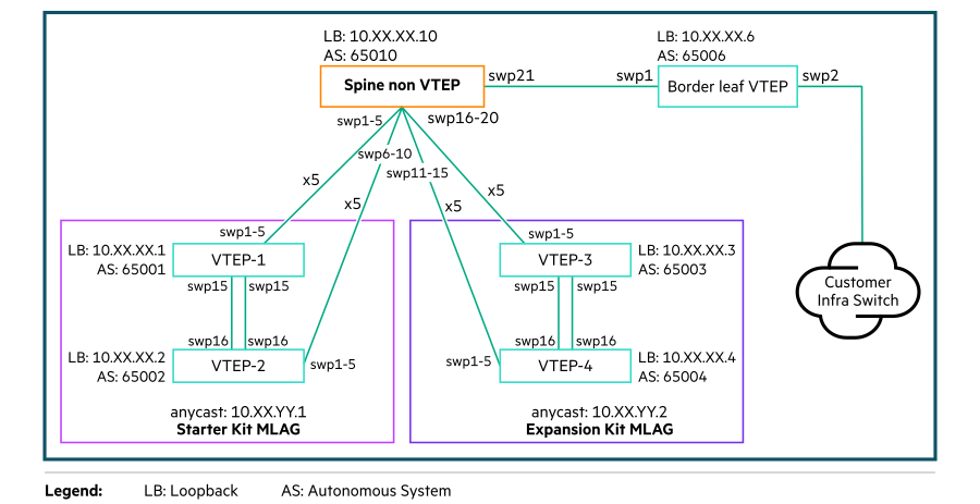
- Spine switch
Spine switches are non-VTEP switches that provide the connectivity between the Data and Border Leaf switches. Spine switches must be configured by the network administrator at the customer end.
- Border Leaf switch
A Border Leaf switch is used for providing the north-south data traffic and connects to the WAN or outside of the fabric. Any leaf within the network follows the default route towards the Border Leaf for all external traffic (towards the Internet or a different device). A Border Leaf switch must be configured with BGP (Border Gateway Protocol) instance by the network administrator at the customer end.
| VLANs | Description |
|---|---|
| iLO-OOBM | ILO network for managing servers. |
| ESXi_MGMT | ESXi Management network for the ESXi host management traffic. |
| vMOTION | vMotion network for VMware vSphere vMotion traffic. |
| vSAN | vSAN Network for vSAN shared storage traffic. |
| VM_MGMT | Virtual Machine Network for the VM Management traffic. |
| VCENTER_HA | vCenter High Availability network. |
| API | VMware Integrated OpenStack (VIO) dashboard is deployed on API network. This network is not configured for access outside the datacenter. NOTE:
If this dashboard needs to be accessed from outside the data center, then configure the API network as an internet routable network. |
| Provider VLAN | Range of VLANs allotted for VM networks. |
| OVERLAY | Overlay Network for Geneve (VTP) Virtual Tunnel Endpoint traffic. |
| EXTERNAL | Range of VLAN's allotted for VM networks. |
| OAM | Operation and Management network provides connectivity to NTP, DNS, LDAP types of infrastructure services in the Data Center. This is a tagged network.
NOTE:
In this document, the OAM is also referred to as customer network. |
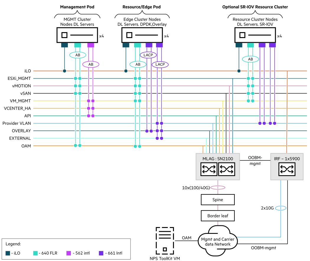
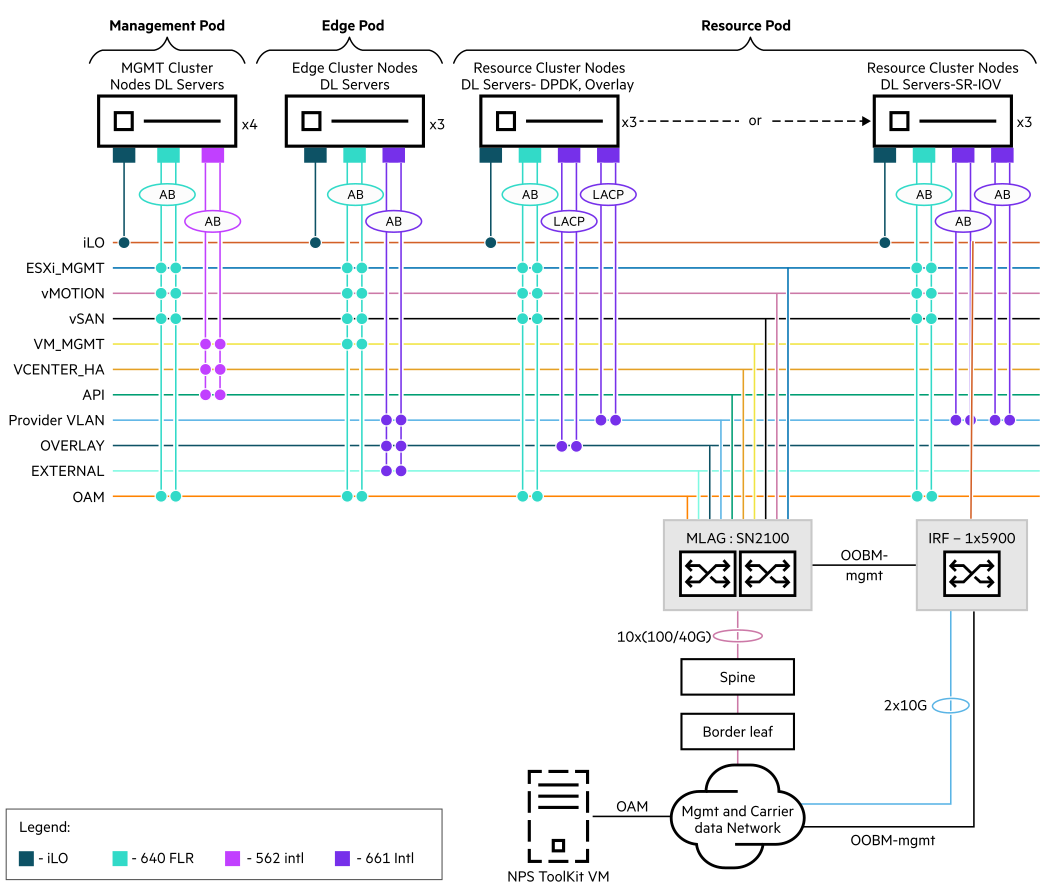
Based on VxLAN solution, the following diagram shows the HPE Telco Blueprint two Pod and three Pod network architecture using HPE components.
Spine and Border Leaf switches topology