Scale out Edge Resource Cluster
The following diagram describes the flow of the scale out edge_resource cluster flow for two pod configuration.
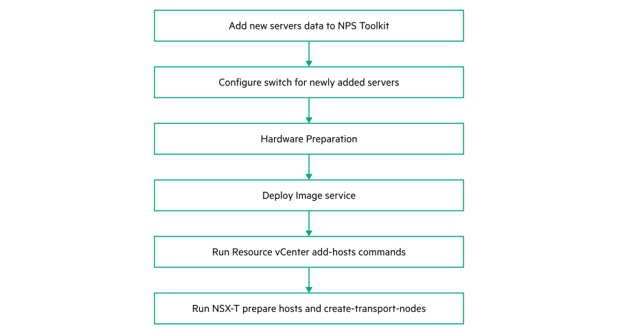
Add new Server data to NPS toolkit
To create a JSON using the TICG, see Generating an input JSON using the TICG for Addon Kits.
To add a new node, use the Addon Servers UI to generate the JSON file and run the following command with the location of the JSON file:
nps add-infra -f <location of the server profile JSON file>NOTE:The JSON file for adding nodes must be generated using the Addon Servers UI only.
- The following is a sample format of the JSON generated using the Addon servers UI:
{
    "topology_name": "<topology_name_same as starter kit>",
    "topology_modules": [
        <topology_modules_of_starter_kit>   ],
    "topology_data": {
        "infra": {
            "servers": [
                {
                    "description": "Description",
                    "hostname": ""<Name of the server>",
                    "hw_profile": "<Name of the server profile>",
                    "ilo": "<IP address of iLO>",
                    "user": ""<User name>",
                    "password": ""<password>",
                    "role": "<Role of the server>",
                    "model": "<Model of the server"
                }
            ],
            "oobm_type": "manual",
            "description": "<description>"
        }
    }
}
- Run the following command to verify the list of servers.
#nps show --data servers
Configure switch for newly added servers
- Prerequisites
Ensure that for a newly added Resource-Edge server FLR1, FLR2, PCI1.1, PCI1.2, PCI3.1 and PCI3.2 ports needs to be connected to Cumulus 2100 switches and ILO port to be connected to 5900 switch as per the Portmap.
Once the connectivity is successfully established, perform the following steps for switch configuration.
- Procedure
Configure the 5900 switch port connected to ILO of the server with ILO VLAN.
For example. if switch port for ILO is GE1/0/12Connect to 5900 switch through SSH using Management IP.
- Switch to system view using the following command:
From System view, return to the User View by entering Ctrl+Z.<R12-N2840-U36-5900 >sys[R12-N2840-U36-5900-ILO] - Configure ILO VLAN as access port for port GE1/0/12 as shown in the following example:
[R12-N2840-U36-5900]int g 1/0/12 [R12-N2840-U36-5900-GigabitEthernet1/0/12]port access vlan <vlan id for ILO> - Save the configuration using the following command:
[R12-N2840-U36-5900-GigabitEthernet1/0/12]save
Validating file. Please wait...
Saved the current configuration to mainboard device successfully.
Configure 2100 cumulus switch ports for FLR1 and FLR2 ports of the newly added server. FLR1 port of the server is connected to cumulus 2100 switch 1 and FLR2 is connected to Cumulus 2100 switch 2.
In this example, the newly added server (RE-N10) FLR1 is connected to port swp6s0 of 2100 switch1 and swp6s0 of 2100 switch2. FLR1 & FLR2 are configured as active-backup mode with the VLANS ESXI_MGMT (Untagged), VSAN, VMOTION, OAM and VM-MGMT.Connect to 2100 switch1 through SSH using management IP.
- Run the following commands:
$ net add interface swp6s0 alias RE_N10_640_p1
$ net add interface swp6s0 bridge vids < ESXI_MGMT,VSAN,VMOTION,OAM,VM- MGMT>
$ net add interface swp6s0 bridge pvid < ESXI_MGMT>
$ net commit
Connect to 2100 switch 2 through SSH using management IP.
- Run the following commands:
$ net add interface swp6s0 alias RE_N10_640_p2
$ net add interface swp6s0 bridge vids < ESXI_MGMT,VSAN,VMOTION,OAM VM- MGMT>
$ net add interface swp6s0 bridge pvid < ESXI_MGMT>
$ net commit
Configure 2100 cumulus switch ports for PCI1.1 & PCI1.2 ports of the newly added server.
In a resource-edge server PCI1.1 and PCI1.2 has to be configured as LACP with OVERLAY_NETWORK VLAN in 2100 switches.Connect to 2100 switch1 through SSH using management IP.
- Run the following commands (considering PCI1.1 is connected to swp7s0 in this example):
$ net add interface swp7s0 alias RE_N10_661_1.1
$ net add bond RE-PCI1-N10 bond slaves swp7s0
$ net add bond RE-PCI1-N10 mtu 9216
$ net add bond RE-PCI1-N10 bond lacp-rate slow
$ net add bond RE-PCI1-N10 bridge vids < OVERLAY_NETWORK vlan >
$ net commit
Connect to 2100 switch2 through SSH using management IP.
- Run the following commands (considering PCI1.2 is connected to swp7s0 in this example):
$ net add interface swp7s0 alias RE_N10_661_1.2
$ net add bond RE-PCI1-N10 bond slaves swp7s0
$ net add bond RE-PCI1-N10 mtu 9216
$ net add bond RE-PCI1-N10 bond lacp-rate slow
$ net add bond RE-PCI1-N10 bridge vids < OVERLAY_NETWORKvlan >
$ net commit
Configure 2100 cumulus switch ports for PCI3.1 and PCI3.2 ports of the newly added server.
In a resource-edge server, PCI3.1 and PCI3.2 should be configured as LACP with OVERLAY_NETWORK, EXT_Network and PROVIDER_NET VLANs in 2100 switches.Connect to 2100 switch1 through SSH using management IP.
- Run the following commands (considering PCI3.1 is connected to swp8s0 in this example):
$ net add interface swp8s0 alias RE_N10_661_3.1
$ net add bond RE-PCI3-N10 bond slaves swp8s0
$ net add bond RE-PCI3-N10 mtu 9216
$ net add bond RE-PCI3-N10 bond lacp-rate slow
$ net add bond RE-PCI3-N10 bridge vids < OVERLAY_NETWORK,EXT_Network,PROVIDER_NET  >
$ net commit
Connect to 2100 switch2 through SSH using management IP.
- Run the following commands (considering PCI3.2 is connected to swp8s0 in this example):
$ net add interface swp8s0 alias RE_N10_661_3.2
$ net add bond RE-PCI3-N10 bond slaves swp8s0
$ net add bond RE-PCI3-N10 mtu 9216
$ net add bond RE-PCI3-N10 bond lacp-rate slow
$ net add bond RE-PCI3-N10 bridge vids < OVERLAY_NETWORK,EXT_Network,PROVIDER_NET  >
$ net commit
NOTE:Repeat all these steps for all newly added resource-edge servers.
Hardware Preparation
See Hardware preparation.
Deploy image service
nps baremetal -a delete -nos <nos_type>Run vCenter resource add-host command
#nps deploy -s vcenter_res -a add-hosts --forceLogin to Resource vCenter with valid credentials.
Navigate to Hosts and Cluster. The newly added servers are listed under edge resource cluster.
Run NSX-T prepare-hosts and create transport-nodes command
- Run the following command to prepare the newly added ESXi nodes with NSX driver.
`To verify the status of newly added nodes, perform the following verification steps:#nps deploy -s nsxt -a prepare-hosts --force- Login to NSX-T Manager using valid credentials.
Navigate to Fabric => Nodes
From Managed by option, select the resource vCenter
Expand the edge resource cluster. This resource cluster lists all the ESXi nodes available in the cluster and check the NSX installation status of each ESXi node.
- Run the following command to create transport nodes:
#nps deploy -s nsxt -a create-transport-nodes --forceTo verify the status of newly added prepared host and transport nodes:Login to NSX-T Manager using valid credentials.
Navigate to Fabric => Nodes
Click on Transport Nodes
To check, navigate to Hosts and Cluster. The newly added nodes are listed under edge resource cluster.
Check the Configuration State and Status of each Transport node.
NOTE:The Configuration State should be Success and Status should be Up for all transport nodes.