Addition of SR-IOV Compute Cluster for Two Pod Configuration
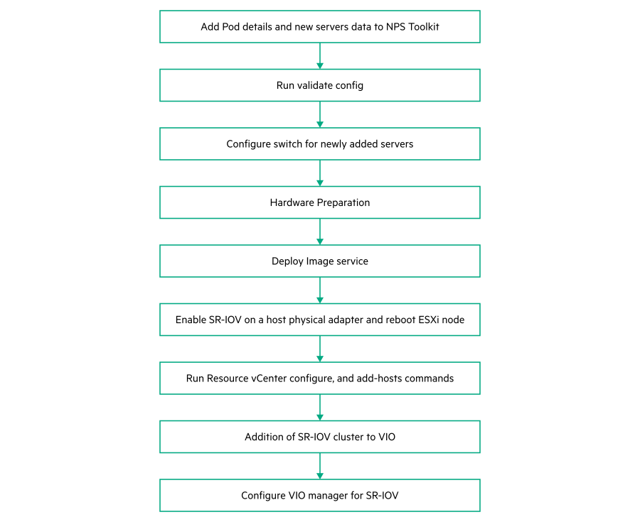
Add pod details and new Servers data to NPS toolkit
Run the following command to add the Pods to the Pod configuration data
#nps add -c vim -n pods –f /root/pods.json #vi pods.json { "profile": "SRIOV", "type": "resource", "storage": "vsan", "name": "<name of the pod>" }NOTE:Profile type is SRIOV. The newly added ESXi server role is the same as name of the pod.
To add a new node, use the Addon Servers UI to generate the JSON file and run the following command with the location of the JSON file:
nps add-infra -f <location of the server profile JSON file>NOTE:The JSON file for adding nodes must be generated using the Addon Servers UI only. To create a JSON using the TICG, see Generating an input JSON using the TICG for Addon Kits.
- The following is a sample format of the JSON generated using the Addon servers UI:
{
    "topology_name": "<topology_name_same as starter kit>",
    "topology_modules": [
        <topology_modules_of_starter_kit>   ],
    "topology_data": {
        "infra": {
            "servers": [
                {
                    "description": "Description",
                    "hostname": ""<Name of the server>",
                    "hw_profile": "<Name of the server profile>",
                    "ilo": "<IP address of iLO>",
                    "user": ""<User name>",
                    "password": ""<password>",
                    "role": "<Role of the server>",
                    "model": "<Model of the server"
                }
            ],
            "oobm_type": "manual",
            "description": "<description>"
        }
    }
}
- Run the following command to verify the list of servers.
#nps show --data servers
Run validate configuration
#nps vim-validate-jsonConfigure switch for newly add servers
- Prerequisites
Ensure that for a newly added Resource-Edge server FLR1, FLR2, PCI1.1, PCI1.2, PCI3.1 and PCI3.2 ports needs to be connected to Cumulus 2100 switches and ILO port to be connected to 5900 switch as per the Portmap.
Once the connectivity is successfully established, perform the following steps for switch configuration.
- Procedure
Configure the 5900 switch port connected to ILO of the server with ILO VLAN.
For example. if switch port for ILO is GE1/0/12Connect to 5900 switch through SSH using Management IP.
- Switch to system view using the following command:
From System view, return to the User View by entering Ctrl+Z.<R12-N2840-U36-5900 >sys[R12-N2840-U36-5900-ILO] - Configure ILO VLAN as access port for port GE1/0/12 as shown in the following example:
[R12-N2840-U36-5900]int g 1/0/12 [R12-N2840-U36-5900-GigabitEthernet1/0/12]port access vlan <vlan id for ILO> - Save the configuration using the following command:
[R12-N2840-U36-5900-GigabitEthernet1/0/12]save
Validating file. Please wait...
Saved the current configuration to mainboard device successfully.
Configure 2100 cumulus switch ports for FLR1 and FLR2 ports of the newly added server.
FLR1 port of the server is connected to cumulus 2100 switch 1 and FLR2 is connected to Cumulus 2100 switch 2.
In this example, the newly added server (RN10) FLR1 is connected to port swp6s0 of 2100 switch1 and swp6s0 of 2100 switch2. FLR1 & FLR2 are configured as active-backup mode with the VLANS ESXI_MGMT (Untagged), VSAN, VMOTION, OAM and VM-MGMT.Connect to 2100 switch1 through SSH using management IP.
- Run the following commands:
$ net add interface swp6s0 alias RE_N10_640_p1
$ net add interface swp6s0 bridge vids < ESXI_MGMT,VSAN,VMOTION,OAM,VM- MGMT>
$ net add interface swp6s0 bridge pvid < ESXI_MGMT>
$ net commit
Connect to 2100 switch 2 through SSH using management IP.
- Run the following commands:
$ net add interface swp6s0 alias RE_N10_640_p2
$ net add interface swp6s0 bridge vids < ESXI_MGMT,VSAN,VMOTION,OAM VM- MGMT>
$ net add interface swp6s0 bridge pvid < ESXI_MGMT>
$ net commit
Configure 2100 cumulus switch ports for PCI1.1, PCI1.2, PCI3.1 & PCI3.2 ports of newly added server
In a resource server with SR-IOV all PCI ports are passed with PROVIDER_NET VLANs. PCI1.1 and PCI3.1 has to be connected to 2100 switch1. PCI1.2 and PCI3.2 are connected to 2100 switch2.Connect to 2100 switch1 through SSH using management IP.
- Run the following commands (considering PCI1.1 is connected to swp7s0 and PCI3.1 is connected to swp8s0 in this example):
$ net add interface swp7s0 alias rn10_661_1.1
$ net add interface swp8s0 alias rn10_661_3.1
$ net add interface swp7s0 bridge vids < PROVIDER_NET vlans >
$ net add interface swp8s0 bridge vids < PROVIDER_NET vlans >
$ net commit
Connect to 2100 switch2 through SSH using management IP.
- Run the following commands (considering PCI1.2 is connected to swp7s0 and PCI3.2 is connected to swp8s0 in this example):
$ net add interface swp7s0 alias rn10_661_1.2
$ net add interface swp8s0 alias rn10_661_3.2
$ net add interface swp7s0 bridge vids < PROVIDER_NET vlans >
$ net add interface swp8s0 bridge vids < PROVIDER_NET vlans >
$ net commit
NOTE:Repeat all these steps for all newly added resource-edge servers.
Hardware Preparation
See Hardware preparation.
Deploy image service
nps baremetal -a delete -nos <nos_type>Enable SR-IOV on a Host Physical Adapter
- Prerequisites
SR-IOV has to be enabled on NICs where ENS driver is installed. If ENS driver is not installed, see Appendix E: Installation of driver post image service configuration. After installing the ENS driver perform the following procedure.
- Procedure
- Login to ESXi node and run the following command to verify the available NIC.
# esxcfg-nics –-list - Run the following command to display the current configuration:
# esxcli system module parameters list -m i40en - Run the following command to enable VFS on Intel(R) Ethernet Controller XXV710 NICs:
For example,# esxcfg-module i40en -s max_vfs=<no vfs>,< no vfs >,< no vfs>,< no vfs ># esxcfg-module i40en -s max_vfs=2,2,2,2 - Run the following command to enable maintenance mode:
# esxcli system maintenanceMode set --enable true Run the following command to get current status of maintenance mode:
# esxcli system maintenanceMode get- Run the following command to reboot ESXI server:
# reboot - Wait until the server is up and run the following command to exit maintenance mode:
# esxcli system maintenanceMode set --enable false - Run the following command to verify the VFs in all the NICs.
# esxcli network sriovnic vf list -n vmnic<number>
Run Resource vCenter, add-hosts and vSAN storage commands
- Run the following command from NPS toolkit VM to create new cluster and its configurations:
# nps deploy -s vcenter_res -a configure --force - Run the following command to add newly added ESXI node to SR-IOV cluster
# nps deploy -s vcenter_res -a add-hosts --force - Run the following command to create vSAN storage to SR-IOV Cluster.
nps deploy -s vcenter-res -a create-storage --force
Addition of SR-IOV cluster to VMware Integrated Openstack
- Procedure
Login to Management vCenter using valid credentials.
Navigate to Home -> VMware openstack-> manage -> novacompute
Click on + to add cluster to Openstack.
Enter the particulars and click Next.
Select the Pod name provided in the Pod creation and click Next.
Select vsandatastore of sriov_pod and click Next.
Verify the particulars and click Finish
A pop-up appears with the message Adding a cluster will restart the nova service, click Ok
Wait for the completion of adding a new cluster to VIO
Configure VIO Manager for SR-IOV
- Prerequisites
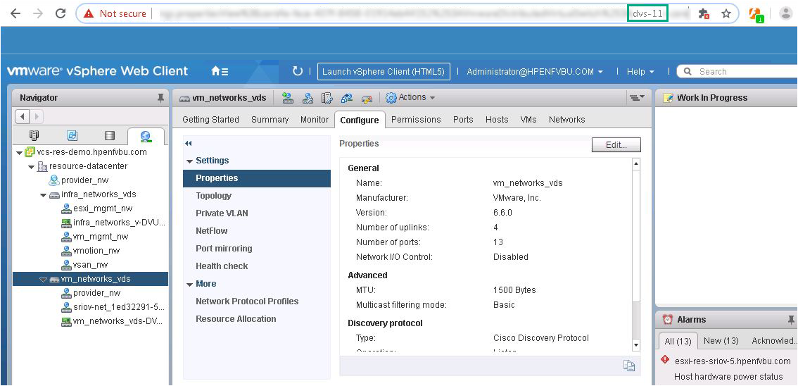
- Login to Resource vCenter using valid credentials.
Navigate to vm_networks_vds on the left.
Make a note of the Moid in the URL.
- Login to Management vCenter server using valid credentials.
Navigate to vio-manager => vio-compute-1 => Click Launch Console.
Login to the newly created compute VM using the default credentials.
- Run the following command to get the hostname.
compute01 is the hostname to be entered in the procedure.root@compute01:~# hostname compute01
- Procedure
Login to VIO manager as a viouser.
- Navigate to custom yml file,
sudo vim /opt/vmware/vio/custom/custom.yml Uncomment nova_dvs_moid section.
- After uncommenting the nova_dvs_moid, enter the dvs moid to custom.yml file.
For example,nova_dvs_moid: compute<id>: dvs-<moid>nova_dvs_moid: compute01: dvs-11NOTE:The moid is ascertained as shown in the Prerequisites section.
- Run the following command to enable SR-IOV:
Wait for the process to complete.sudo viocli deployment configure - Post successful configuration, the following message is displayed:
Success: Completed post deployment configuration.
Now launch SR-IOV VMs using VIO dashboard.