The default network switches can be swapped with another HPE switch model or other third-party switching hardware.
You can configure your network using either VLAN or VxLAN configurations.
VLAN-based network configuration
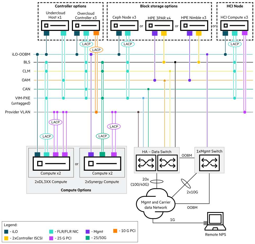
Following is a generic representation of HPE Telco Blueprint network diagram using VLAN-based configuration.
Figure 2: Generic VLAN-based network diagram
VxLAN-based network configuration
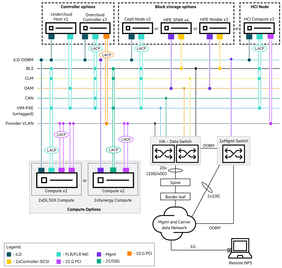
Following is a generic representation of HPE Telco Blueprint network diagram using VxLAN-based configuration.
Figure 3: Generic VxLAN-based network diagram
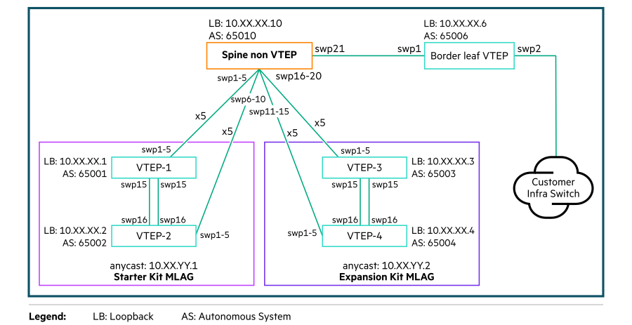
The following diagram provides an overview of sample topology of an Underlay configuration that includes Spine and Border Leaf switch network connectivities to the Blueprint Leaf or ToR switches.
Figure 4: Sample Topology for Underlay configuration