Network activity that fails to meet accepted norms may indicate a hardware problem with one or more of the network components, possibly including the switch. Such problems can also be caused by a network loop or simply too much traffic for the network as it is currently designed and implemented. Unusual network activity is usually indicated by the LEDs on the front of the switch or measured with the switchconsole interface or with a network management tool such as HP PCM+. For information on using LEDs to identify unusual network activity, see the Installation Guide you received with the switch.
A topology loop can also cause excessive network activity. The Event Log "FFI" messages can be indicative of this type of problem.
Broadcast storms may be occurring in the network. These may be caused by redundant links between nodes.
-
If you are configuring a port trunk, finish configuring the ports in the trunk before connecting the related cables. Otherwise you may inadvertently create a number of redundant links (that is, topology loops) that will cause broadcast storms.
-
Turn on STP to block redundant links
-
Check for FFI messages in the Event Log
If you use a DHCP server to assign IP addresses in your network, and you find a device with a valid IP address that does not appear to communicate properly with the server or other devices, a duplicate IP address may have been issued by the server. This can occur if a client has not released a DHCP-assigned IP address after the intended expiration time and the server "leases" the address to another device. This can also happen, For example, if the server is first configured to issue IP addresses with an unlimited duration, and then is subsequently configured to issue IP addresses that will expire after a limited duration. One solution is to configure "reservations" in the DHCP server for specific IP addresses to be assigned to devices having specific MAC addresses. For more information, see the documentation for the DHCP server.
One indication of a duplicate IP address in a DHCP network is this Event Log message:
where both instances of IP-address are the same address, indicating that the IP address has been duplicated somewhere on the network.
When the switch is first configured for DHCP/Bootp operation, or if it is rebooted with this configuration, it immediately begins sending request packets on the network. If the switch does not receive a reply to its DHCP/Bootp requests, it continues to periodically send request packets, but with decreasing frequency. Thus, if a DHCP or Bootp server is not available or accessible to the switch when DHCP/Bootp is first configured, the switch may not immediately receive the desired configuration.
After verifying that the server has become accessible to the switch, reboot the switch to re-start the process.
-
The switch may be running with IP routing disabled. To ensure that IP routing is enabled, execute
show runningand look for the IP routing statement in the resulting listing. For Example:Indication that routing is enabled
HP Switch(config)# show running
Running configuration:
; J9091A Configuration Editor; Created on release #XX.15.06
hostname " HPswitch "
ip default-gateway 10.33.248.1
ip routing


logging 10.28.227.2
snmp-server community "public" Unrestricted
ip access-list extended "Controls for VLAN 20"
permit tcp 0.0.0.0 255.255.255.255 10.10.20.98 0.0.0.0 eq 80
permit tcp 0.0.0.0 255.255.255.255 10.10.20.21 0.0.0.0 eq 80
deny tcp 0.0.0.0 255.255.255.255 10.10.20.1 0.0.0.255 eq 80
deny tcp 10.10.20.1? 0.0.0.0 10.10.10.100 0.0.0.0 eq 20 log
deny tcp 10.10.20.20 0.0.0.0 10.10.10.100 0.0.0.0 eq 20 log
deny tcp 10.10.20.43 0.0.0.0 10.10.10.100 0.0.0.0 eq 20 log
permit ip 10.10.20.1 0.0.0.255 10.10.10.100 0.0.0.0
deny ip 10.10.30.1 0.0.0.255 10.10.10.100 0.0.0.0
permit ip 10.10.30.1 0.0.0.255 10.10.10.1 0.0.0.255
exit
![[NOTE: ]](images/note.gif)
NOTE: If an ACL assigned to a VLAN includes an ACE referencing an IP address on the switch itself as a packet source or destination, the ACE screens traffic to or from this switch address regardless of whether IP routing is enabled. This is a security measure designed to help protect the switch from unauthorized management access.
If you need to configure IP routing, execute the
ip routingcommand. -
ACL filtering on the switches applies only to routed packets and packets having a destination IP address (DA) on the switch itself.
Also, the switch applies assigned ACLs only at the point where traffic enters or leaves the switch on a VLAN. Ensure that you have correctly applied your ACLs ("in" and/or "out") to the appropriate VLANs.
The implicit deny any function that the switch automatically applies as the last entry in any ACL always blocks packets having the same DA as the switch's IP address on the same VLAN. That is, bridged packets with the switch itself as the destination are blocked as a security measure.
To preempt this action, edit the ACL to include an ACE that permits access to the switch's DA on that VLAN from the management device.
When using the "host" option in the Command syntax, ensure that you are not including a mask in either dotted decimal or CIDR format. Using the "host" option implies a specific host device and therefore does not permit any mask entry.
Correctly and incorrectly specifying a single host
Switch(config)# access-list 6 permit host 10.28.100.100Invalid input: 255.255.255.255 Switch(config)# access-list 6 permit host 10.28.100.100/32
Invalid input: 10.28.100.100/32
Where the log statement is included in multiple ACEs configured with a "deny" option, a large volume of "deny" matches generating logging messages in a short period of time can impact switch performance. If it appears that the switch is not consistently logging all "deny" matches, try reducing the number of logging actions by removing the log statement from some ACEs configured with the "deny" action.
The implicit deny any function that the switch automatically applies as the last entry in any ACL may be blocking all access by devices not specifically permitted by an entry in an ACL affecting those sources. If you are using the ACL to block specific hosts, a group of hosts, or a subnet, but want to allow any access not specifically permitted, insert permit any as the last explicit entry in the ACL.
Two possible causes of this problem are:
-
Routing is not enabled. If
show runningindicates that routing is not enabled, use theip routingcommand to enable routing. -
An ACL may be blocking access to the VLAN (on a switch covered in this guide). Ensure that the switch's IP address on the VLAN is not blocked by one of the ACE entries in an ACL applied to that VLAN. A common mistake is to either not explicitly permit the switch's IP address as a DA or to use a wildcard ACL mask in a
denystatement that happens to include the switch's IP address. For an Example: of this problem, see section "General ACL Operating Notes" in the "Access Control Lists (ACLs)" chapter of the latest Access Security Guide for your switch.
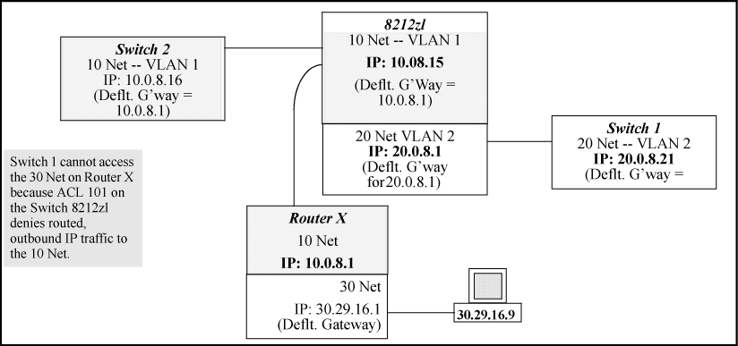
Configuring a "deny" ACE that includes a gateway address can block traffic attempting to use the gateway as a next-hop.
Configuring ACL "101" (ACE blocking an entire subnet) and applying it outbound on VLAN 1 in Inadvertently blocking a gateway includes the router gateway (10.0.8.1) needed by devices on other networks. This can prevent the switch from sending ARP and other routing messages to the gateway router to support traffic from authorized remote networks.
In Inadvertently blocking a gateway, this ACE (see data in bold below) denies access to the 10 Net's 10.0.8.1 router gateway needed by the 20 Net (Subnet mask is 255.255.255.0).
ACE blocking an entire subnet
HP Switch(config)# access-list config

ip access-list extended "101"


deny ip 0.0.0.0 255.255.255.255 10.0.8.30 0.0.0.255
  permit ip 0.0.0.0 255.255.255.255 0.0.0.00 255.255.255.255
  exit
To avoid inadvertently blocking the remote gateway for authorized traffic from another network (such as the 20 Net in this Example:):
-
Configure an ACE that specifically permits authorized traffic from the remote network.
-
Configure narrowly defined ACEs to block unwanted IP traffic that would otherwise use the gateway; such ACEs might deny traffic for a particular application, particular hosts, or an entire subnet.
-
Configure a "permit any" ACE to specifically allow any IP traffic to move through the gateway.
If you use the switch as a gateway for traffic you want routed between subnets, use these general steps to avoid blocking the gateway for authorized applications:
-
Configure gateway security first for routing with specific permit and deny statements.
-
Deny any unauthorized traffic that you have not already denied in step Step 1.
IGMP must be enabled on the switch and the affected port must be configured for "Auto" or "Forward" operation.
The IGMP feature does not operate if the switch or VLAN does not have an IP address configured manually or obtained through DHCP/Bootp. To verify whether an IP address is configured for the switch or VLAN, do one of the following:
-
Try using the WebAgent: If you can access the WebAgent, then an IP address is configured.
-
Try to telnet to the switch console: If you can Telnet to the switch, an IP address is configured.
-
Use the switch console interface: From the Main Menu, check the Management Address Information screen by clicking on:
In this case, the switch displays the following message:
You cannot enable LACP on a port while it is configured as a static Trunk port. To enable LACP on a static-trunked port:
|
|
|
![[CAUTION: ]](images/caution.gif) |
CAUTION: Removing a port from a trunk without first disabling the port can create a traffic loop that can slow down or halt your network. Before removing a port from a trunk, HP recommends that you either disable the port or disconnect it from the LAN. |
|
|
See also Radius-related problems.
In this case, the switch attempts authentication using the secondary method configured for the type of access you are using (console, Telnet, or SSH).
There can be several reasons for not receiving a response to an authentication request. Do the following:
-
Use
pingto ensure that the switch has access to the configured RADIUS servers. -
Verify that the switch is using the correct encryption key (RADIUS secret key) for each server.
-
Verify that the switch has the correct IP address for each RADIUS server.
-
Ensure that the
radius-server timeoutperiod is long enough for network conditions.
If the RADIUS server configuration for authenticating the client includes a VLAN assignment, ensure that the VLAN exists as a static VLAN on the switch. See "How 802.1X Authentication Affects VLAN Operation" in the Access Security Guide for your switch.
If the affected VLAN is configured as untagged on the port, it may be temporarily blocked on that port during an 802.1X session. This is because the switch has temporarily assigned another VLAN as untagged on the port to support the client access, as specified in the response from the RADIUS server. See "How 802.1X Authentication Affects VLAN Operation" in the Access Security Guide for your switch.
If aaa authentication port-access is configured for Local, ensure that you have entered the local login (operator-level) username and password of the authenticator switch into the identity and secret parameters of the supplicant configuration. If instead, you enter the enable (manager-level) username and password, access will be denied.
The link to the authenticator may have been moved from one port to another without the supplicant statistics having been cleared from the first port. See "Note on Supplicant Statistics" in the chapter on Port-Based and User-Based Access Control in the Access Security Guide for your switch.
802.1X is not active on the switch. After you execute aaa port-access authenticator active, all ports configured with control unauthorized should be listed as Closed.
Authenticator ports remain "open" until activated
HP Switch(config)# show port-access authenticator e 9 Port Access Authenticator Status Port-access authenticator activated [No] : No Access Authenticator Authenticator Port Status Control State Backend State ---- ------ -------- -------------- -------------- 9 Open
Use show radius to verify that the encryption key (RADIUS secret key) the switch is using is correct for the server being contacted. If the switch has only a global key configured, it either must match the server key or you must configure a server-specific key. If the switch already has a server-specific key assigned to the server's IP address, it overrides the global key and must match the server key.
Displaying encryption keys
HP Switch(config)# show radius
 Status and Counters - General RADIUS Information
  Deadtime(min) : 0
  Timeout(secs) : 5
  Retransmit Attempts : 3
  Global Encryption Key : My-Global-Key
  Dynamic Authorization UDP Port : 3799

                  Auth Acct DM/ Time
  Server IP Addr  Port Port CoA Window Encryption Key
  --------------- ---- ---- --- ------ ---------------
  10.33.18.119    1812 1813            119-only-key
Also, ensure that the switch port used to access the RADIUS server is not blocked by an 802.1X configuration on that port. For example, show port-access authenticator < gives you the status for the specified ports. Also, ensure that other factors, such as port security or any 802.1X configuration on the RADIUS server are not blocking the link.port-list>
If the port is force-authorized with aaa port-access authenticator < command and port security is enabled on the port, then executing port-list> control authorizedinitialize causes the port to clear the learned address and learn a new address from the first packet it receives after you execute initialize.
In this case, the switch attempts authentication using the secondary method configured for the type of access you are using (console, Telnet, or SSH).
There can be several reasons for not receiving a response to an authentication request. Do the following:
-
Use
pingto ensure that the switch has access to the configured RADIUS server. -
Verify that the switch is using the correct encryption key for the designated server.
-
Verify that the switch has the correct IP address for the RADIUS server.
-
Ensure that the
radius-server timeoutperiod is long enough for network conditions. -
Verify that the switch is using the same UDP port number as the server.
|
|
|
|
|
NOTE: Because of an inconsistency between the Windows XP 802.1x supplicant timeout value and the switch default timeout value, which is 5, when adding a backup RADIUS server, set the switch radius-server timeout value to 4. Otherwise, the switch may not failover properly to the backup RADIUS server. |
|
|
Use show radius to verify that the encryption key the switch is using is correct for the server being contacted. If the switch has only a global key configured, it either must match the server key or you must configure a server-specific key. If the switch already has a server-specific key assigned to the server's IP address, it overrides the global key and must match the server key.
Global and unique encryption keys
Switch(config)# show radius Status and Counters - General RADIUS Information Deadtime(min) : 0 Timeout(secs) : 5 Retransmit Attempts : 3 Global Encryption Key : My-Global-Key
This can occur when there are physical loops (redundant links) in the topology. Where this exists, you should enable MSTP on all bridging devices in the topology to detect the loop.
In 802.1Q-compliant switches, MSTP blocks redundant physical links even if they are in separate VLANs. A solution is to use only one, multiple-VLAN (tagged) link between the devices. Also, if ports are available, you can improve the bandwidth in this situation by using a port trunk. See "Spanning Tree Operation with VLANs" in chapter "Static Virtual LANs (VLANs)" in the Advanced Traffic Management Guide for your switch.
Some of the problems that can result from incorrect use of fast-uplink MSTP include temporary loops and generation of duplicate packets.
-
Fast-uplink is configured on a switch that is the MSTP root device.
-
Either the
Hello Timeor theMax Agesetting (or both) is too long on one or more switches. Return theHello TimeandMax Agesettings to their default values (2 seconds and 20 seconds, respectively, on a switch). -
A "downlink" port is connected to a switch that is further away (in hop count) from the root device than the switch port on which fast-uplink MSTP is configured.
-
Two edge switches are directly linked to each other with a fast-uplink (Mode =
Uplink) connection. -
A switch serving as a backup MSTP root switch has ports configured for fast-uplink MSTP and has become the root device because of a failure in the original root device.
Even though you have placed the client's public key in a text file and copied the file (using the copy tftp pub-key-file command) into the switch, the switch refuses to allow the client to have access. If the source SSH client is an SSHv2 application, the public key may be in the PEM format, which the switch (SSHv1) does not interpret. Check the SSH client application for a utility that can convert the PEM-formatted key into an ASCII-formatted key.
The switch does not have a host key. Verify by executing show ip host-public-key. If you see the message
you need to generate an SSH key pair for the switch. To do so, execute crypto key generate (see "Generating the switch's public and private key pair" in the SSH chapter of the Access Security Guide for your switch.)
The client's public key entry in the public key file may be preceded by another entry that does not terminate with a new line (CR). In this case, the switch interprets the next sequential key entry as simply a comment attached to the preceding key entry. Where a public key file has more than one entry, ensure that all entries terminate with a new line (CR). While this is optional for the last entry in the file, not adding a new line to the last entry creates an error potential if you either add another key to the file at a later time or change the order of the keys in the file.
Download failed: overlength key in key file.Download failed: too many keys in key file.Download failed: one or more keys is not a valid RSA public key.
The public key file you are trying to download has one of the following problems:
The switch does not support data compression in an SSH session. Clients often have compression turned on by default, but then disable it during the negotiation phase. A client that does not recognize the compression-request FAILURE response may fail when attempting to connect. Ensure that compression is turned off before attempting a connection to prevent this problem.
When troubleshooting TACACS+ operation, check the switch's Event Log for indications of problem areas.
If the switch is functioning properly, but no username/password pairs result in console or Telnet access to the switch, the problem may be caused by how the TACACS+ server and/or the switch are configured. Use one of the following methods to recover:
-
Access the TACACS+ server application and adjust or remove the configuration parameters controlling access to the switch.
-
If the above method does not work, try eliminating configuration changes in the switch that have not been saved to flash (boot-up configuration) by causing the switch to reboot from the boot-up configuration (which includes only the configuration changes made prior to the last
write memorycommand.) If you did not usewrite memoryto save the authentication configuration to flash, pressing theResetbutton reboots the switch with the boot-up configuration. -
Disconnect the switch from network access to any TACACS+ servers and then log in to the switch using either Telnet or direct console port access. Because the switch cannot access a TACACS+ server, it defaults to local authentication. You can then use the switch's local Operator or Manager username/password pair to log on.
-
As a last resort, use the
Clear/Resetbutton combination to reset the switch to its factory default boot-up configuration. Taking this step means you will have to reconfigure the switch to return it to operation in your network.
If the switch can access the server device (that is, it can ping the server), a configuration error may be the problem. Some possibilities include:
-
The server IP address configured with the switch's
tacacs-serverhostcommand may not be correct. (Use the switch'sshow tacacs-servercommand to list the TACACS+ server IP address.) -
The encryption key configured in the server does not match the encryption key configured in the switch (by using the
tacacs-server keycommand). Verify the key in the server and compare it to the key configured in the switch. (Useshow tacacs-serverto list the global key. Useshow configorshow config runningto list any server-specific keys.) -
The accessible TACACS+ servers are not configured to provide service to the switch.
Some reasons for denial include the following parameters controlled by your TACACS+ server application:
For more help, see the documentation provided with your TACACS+ server application.
When using the monitor port in a multiple-VLAN environment, the switch handles broadcast, multicast, and unicast traffic output from the monitor port as follows:
-
If the monitor port is configured for tagged VLAN operation on the same VLAN as the traffic from monitored ports, the traffic output from the monitor port carries the same VLAN tag.
-
If the monitor port is configured for untagged VLAN operation on the same VLAN as the traffic from the monitored ports, the traffic output from the monitor port is untagged.
-
If the monitor port is not a member of the same VLAN as the traffic from the monitored ports, traffic from the monitored ports does not go out the monitor port.
If multiple VLANs are being used on ports connecting 802.1Q-compliant devices, inconsistent VLAN IDs may have been assigned to one or more VLANs. For a given VLAN, the same VLAN ID must be used on all connected 802.1Q-compliant devices.
One or more VLANs may not be properly configured as "Tagged" or "Untagged." A VLAN assigned to a port connecting two 802.1Q-compliant devices must be configured the same on both ports. For example, VLAN_1 and VLAN_2 use the same link between switch "X" and switch "Y," as shown in Example: of correct VLAN port assignments on a link.
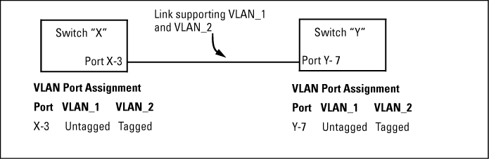
-
If VLAN_1 (VID=1) is configured as "Untagged" on port 3 on switch "X," it must also be configured as "Untagged" on port 7 on switch "Y." Make sure that the VLAN ID (VID) is the same on both switches.
-
Similarly, if VLAN_2 (VID=2) is configured as "Tagged" on the link port on switch "A," it must also be configured as "Tagged" on the link port on switch "B." Make sure that the VLAN ID (VID) is the same on both switches.
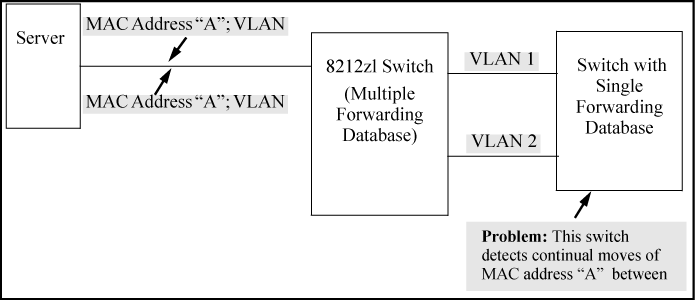
The switches operate with multiple forwarding databases. Thus, duplicate MAC addresses occurring on different VLANs can appear where a device having one MAC address is a member of more than one 802.1Q VLAN, and the switch port to which the device is linked is using VLANs (instead of MSTP or trunking) to establish redundant links to another switch. If the other device sends traffic over multiple VLANs, its MAC address consistently appears in multiple VLANs on the switch port to which it is linked.
Be aware that attempting to create redundant paths through the use of VLANs causes problems with some switches. One symptom is that a duplicate MAC address appears in the Port Address Table of one port and then later appears on another port. While the switches have multiple forwarding databases and thus do not have this problem, some switches with a single forwarding database for all VLANs may produce the impression that a connected device is moving among ports because packets with the same MAC address but different VLANs are received on different ports. You can avoid this problem by creating redundant paths using port trunks or spanning tree.
Previous software versions allowed configuration of VLAN IP addresses in overlapping subnets which can cause incorrect routing of packets and result in IP communication failure. As of software version WB.15.09, overlapping subnet configurations are no longer allowed. An overlapping subnet is determined by the configuration order. The subnet that is configured first is valid, but any subsequent IP addresses that overlap are not allowed.
When the switch is booted into software version WB.15.09 or later, and the configuration file includes overlapping subnets, the following occurs:
-
The event log provides an error message in the format:
ip: VLANx : IP initialization failed for vlan x.
For a multinetted VLAN (multiple IP addresses assigned to the VLAN), only the IP addresses that are overlapping subnets are removed. The other IP addresses on the VLAN are retained and function correctly. The error message can be somewhat misleading; the IP addresses on the VLAN that are not overlapping are initialized correctly.
-
The output of the
show ipcommand correctly indicates that the overlapping IP address does not exist on the VLANs that have error messages in the event log. -
The output of the
show running-configcommand incorrectly indicates that the overlapping IP address is configured. In An IP address that is not actually configured on the VLAN, the IP address shown in VLAN6 is not actually configured on the VLAN; it has been removed.An IP address that is not actually configured on the VLAN
HP Switch(config)# show running-config

.
.
.
  vlan 5
     name “VLAN5”
     ip address 11.22.33.1 255.0.0.0
     exit
  vlan 6
     name “VLAN6”
     ip address 11.23.34.1 255.255.255.0
     exit
The information is retained in the config file to allow you to boot up the switch and have it function as it did when it was configured with earlier software that allows overlapping subnets.
If you attempt to remove the overlapping subnet from the VLAN, the switch displays an error message similar to:
The IP address <

ip-address> is not configured on this VLAN
This occurs because the overlapping IP address has been removed and is not visible to the switch. To resolve this:
-
Enter the
show ipcommand to determine which addresses are visible to the switch. -
Remove the erroneous IP addresses from the config file by entering the
no ip addresscommand to remove all the IP addresses from the specific VLAN. Be sure to document the other valid IP addresses on that VLAN so they can be restored after removing the erroneous IP addresses from the config file.
If you go back to a software version prior to WB.15.09 before removing the overlapping IP address, the prior software version enables the overlapping IP subnet.
When two or more fans fail, a two-minute timer starts. After two minutes, the switch is powered down and must be rebooted to restart it. This protects the switch from possible overheating.
HP recommends that you replace a failed fan tray assembly within one minute of removing it.
In traditional HP switches, the state of a link is driven directly by the reported state of the port, which is required for rapid detection of link faults. However, the consequence of this is that a marginal transceiver, optical, or wire cabling, one that "flaps" up and down several times per second, can cause STP and other protocols to react poorly, resulting in a network outage. The link-flap option expands the functionality of the existing fault finder function to include a "link-flap" event and a new action of "warn-and-disable." Together, these additions allow the errant condition to be detected, and the port in question can be optionally disabled.
Syntax:
Default settings: Sensitivity = Medium; Action = Warn
Sensitivity thresholds are static. In a 10-second window, if more than the threshold number of link state transitions (up or down) are detected, the event is triggered. The 10-second window is statically determined, that is, the counters are reset every 10 seconds, as opposed to being a sliding window. The counters are polled twice per second (every 500 milliseconds), and the event is triggered if the sensitivity threshold is crossed at that time.
Configuring the link-flap event and corresponding action applies to all ports and port types (it is a global setting per FFI event type). Note that normal link transition protocols may prevent link state changes from occurring fast enough to trigger the event for some port types, configurations, and sensitivity settings.
When the link-flap threshold is met for a port configured for warn (For example, fault-finder link-flap sensitivity medium action warn), the following message is seen in the switch event log.
When the link-flap threshold is met for a port configured for warn-and-disable (For example, fault-finder linkflap sensitivity medium action warn-and-disable), the following messages are seen in the switch event log.
02672 FFI: port <number>-Excessive link state transitions02673 FFI: port <number>-Port disabled by Fault-finder.02674 FFI: port <number>-Administrator action required to re-enable.
The warn-and-disable action is available for all fault-finder events on an individual basis. It may be used, For example, to disable a port when excessive broadcasts are received. Because the fault-generated disabling of a port requires operator intervention to re-enable the port, such configuration should be used with care. For example, link-flap-initiated disablement is not desired on ports that are at the client edge of the network, because link state changes there are frequent and expected.
HP does not recommend automatic disabling of a port at the core or distribution layers when excessive broadcasts are detected, because of the potential to disable large parts of the network that may be uninvolved and for the opportunity to create a denial-of-service attack.
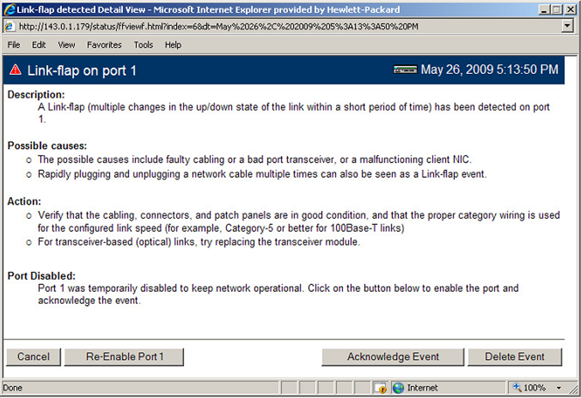
Within the Web Management interface, double-clicking an event on a port that was configured with warn-and-disable and that has met the threshold to trigger the disable action brings up a dialog box with the event details, as shown in Link-flap on port 1 event detail dialog box. The event dialog box now contains a button at the bottom of the page, which can be used to re-enable the disabled port. The button remains, even if the port has already been brought up through a prior exercise of it, or if the port was re-enabled via some other interface (For example, the command line). Re-enabling an already enabled port has no effect. The button to acknowledge the event remains unchanged.
HP switches feature automatic fault detection, which helps protect against network loops and defective equipment. The fault detection sensitivity setting determines the types of alerts reported to the Alert Log based on their level of severity or sensitivity. The sensitivity levels are:
-
High Sensitivity. This policy directs the switch to send all alerts to the Alert Log. This setting is most effective on networks that have none or few problems.
-
Medium Sensitivity. This policy directs the switch to send alerts related to network problems to the Alert Log. If you want to be notified of problems which cause a noticeable slowdown on the network, use this setting.
-
Low Sensitivity. This policy directs the switch to send only the most severe alerts to the Alert Log. This policy is most effective on a network where there are normally a lot of problems and you want to be informed of only the most severe ones
-
Disabled. Disables the Alert Log and transmission of alerts (traps) to the management server (in cases where a network management tool such as ProCurve Manager is in use). Use this option when you don’t want to use the Alert Log.
Enter this CLI command to enable fault detection:
Syntax:
Enables or disables Fault Finder and sets sensitivity.
When the
warn-and-disableaction option is configured, Fault Finder may also shut down a bad port in addition to sending an alert to the Alert Log.Default setting:
fault-finder sensitivity medium action warn
Examples:
To set Fault Finder with a high sensitivity to issue a warning and then disable a port on which there is a high collision or drop rate, you could configure these options:
To set Fault Finder with a medium sensitivity to issue a warning about excessive CRC or alignment errors on a port, you could configure these options:
To set Fault Finder with a low sensitivity to issue a warning about rapid detection of link faults, you could configure these options:
To disable Fault Finder, enter this command:
Fault finder sensitivities for supported conditions
| Condition triggering fault finder | Sensitivities | Units (in packets) | Time period | Fault finder reacts: | ||
|---|---|---|---|---|---|---|
| High | Medium | Low | ||||
| Bad driver — Too many under-sized packets or too many giant packets | 6 | 21 | 36 | 1/10,000 Incoming | 20 secs |
If (undersized/total) >= (sensitivity/10,000) Or If (giant/total) >= (sensitivity/ 10,000) |
| Bad transceiver — Excessive jabbering -Jabbers: (Jabbers are packets longer than the MTU) -Fragments: (packets shorter than they should be) |
6 5 |
21 10 |
36 14 |
1/10,000 Incoming One Fragments |
20 secs 20 secs |
If (jabbers/total) >= (sensitivity/10,000) Or If fragment count in the last 20 seconds >= sensitivity |
| Bad cable — Excessive CRC/ alignment errors | 6 | 21 | 36 | 1/10,000 Incoming | 20 secs |
If (CRC and alignment errors/ total) >= (sensitivity/10,000) |
| Too Long Cable — Excessive late collisions (a late collision error occurs after the first 512 bit times) | 6 | 21 | 36 | 1/10,000 Outgoing | 20 secs |
If (late collisions/total) >= (sensitivity/10,000) |
|
Over bandwidth -High collision rate -High drop rate |
6 65 |
21 257 |
36 449 |
1/10,000 Outgoing One Packet |
5 mins 5 mins |
If (excessive collisions/total) >= (sensitivity/10,000) The count of dropped packets >= sensitivity during the last 5 minutes. |
| Broadcast storm — Excessive broadcasts | 2750 | 9200 | 15600 | One Broadcast Packet | 1 sec |
If the average per second of broadcast packets in the last 20 seconds >= sensitivity |
| Duplex mismatch HDx | 6 | 21 | 36 | 1/10,000 Outgoing | 20 sec |
If (late collisions/total) >= (sensitivity/10,000) |
| Duplex mismatch FDx | 6 | 21 | 36 | 1/10,000 Incoming | 20 sec |
If (CRC and alignment errors/ total) >= (sensitivity/10,000) |
| Link flap — Excessive transitions between link-up and link-down states. | 4 | 7 | 11 | One Transitions | 10 secs |
If the Transition count in the last 10s >= sensitivity. |
Example: of sensitivity calculation:
If a sensitivity is set to High, and a bad cable is causing 15 CRC errors out of a total of 3500 packets transmitted in a 20 second period: