The MSTP VLAN configuration enhancement allows you to preconfigure an MSTP regional topology and ensure that the same VLAN ID-to-MSTI assignments exist on each MSTP switch in the region.
|
|
|
![[CAUTION: ]](images/caution.gif) |
CAUTION: When this software version is installed, the prior VLAN ID-to-MSTI mappings do not change. However, this enhancement is not backward-compatible. If you install a software version earlier than this version and you have configured MSTI entries instances mapped to VLANs, they will be removed from the configuration file when booting to the prior version of software. Do one of the following to install or reload a prior version of the software:
|
|
|
The default behavior of the spanning-tree instance vlan command changes so that, before a static VLAN is configured or a dynamic VLAN is learned on the switch, you can preconfigure its VLAN ID-to-MSTI mapping. Later, when the VLAN is created, it is automatically assigned to the MSTI to which it was previously mapped.
By supporting preconfigured VLAN ID-to-MSTI topologies, the VLAN configuration enhancement provides the following benefits:
-
Scalability: In a network design in which you plan to use a large number of VLANs, you can preconfigure identical VLAN ID-to-MSTI mappings on all switches in a single, campus-wide MST region, regardless of the specific VLANs that you later configure on each switch. After the initial VLAN ID-to-MSTI mapping, you can decide on the exact VLANs that you need on each switch.
All switches in a region must be configured with the same VLAN ID-to-MSTI mappings and the same MSTP configuration identifiers (region name and revision number).
-
Flexibility: By preconfiguring identical VLAN ID-to-MSTI mappings on all switches in an MST region, you can combine switches that support different maximum numbers of VLANs.
-
Network stability: You can reduce the interruptions in network connectivity caused by the regeneration of spanning trees in the entire network each time a configuration change in VLAN-to-MSTI mapping is detected on a switch. The negative impact on network performance is reduced if all newly created VLANs are pre-mapped to the correct MST instances. Later, VLAN creation and deletion are ignored by MSTP and no interruption in spanning tree traffic occurs.
-
Usability: Dynamically learned GVRP VLANs can be mapped to MSTIs and support MSTP load balancing.
When configuring an MSTP regional topology, multiple spanning tree instances are created. Each MST instance provides a fully connected active topology for a particular set of VLANs.
Each switch in an MSTP region is configured with the following set of common parameters:
-
Region name (
spanning-tree config-name) -
Region revision number (
spanning-tree config-revision) -
Identical VLAN ID-to-MSTI mapping (
spanning-tree instance vlan)
Syntax:
Configuring MSTP on the switch automatically configures the IST instance and places all statically and dynamically configured VLANs on the switch into the IST instance. This command creates a new MST instance (MSTI) and moves the VLANs specified from the IST to the MSTI.
You must map at least one VLAN to an MSTI when you create it. You cannot map a VLAN ID to more than one instance. You can create up to 16 MSTIs in a region.
The
noform of the command removes one or more VLANs from the specified MSTI. If no VLANs are specified, thenoform of the command deletes the specified MSTI.When removing a VLAN from an MSTI, the VLAN returns to the IST instance, where it remains or is re-assigned to another MSTI configured in the region.
NOTE: The valid VLAN IDs to map to a specified MSTI are from 1 to 4094. The VLAN ID-to-MSTI mapping does not require a VLAN to be already configured on the switch. The MSTP VLAN enhancement allows preconfiguring MSTP topologies before the VLAN IDs associated with each instance exist on a switch.
When using preconfigured VLAN ID-to-MSTI topologies, ensure that MSTP switches remain in the same region by mapping all VLAN IDs used in the region to the same MSTIs on each regional switch.
Each MST instance supports a different set of VLANs. A VLAN that is mapped to an MST instance cannot be a member of another MST instance.
Mapping VLANs to MSTP Instance
If VLANs 1, 5 and 7 are currently present and you enter the following command, all the VLANs from 1 through 10 are included, even those VLANs that are not present.
HP Switch(config)#: spanning-tree instance 1 vlan 1-10
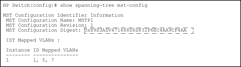
On HP switches other than those covered by this guide, only the VLANs that are present will be included, that is, only VLANs 1, 5 and 7. The switch will map these VLANs to MSTP Instance 1, which results in a Configuration Digest that is not the same as the Configuration Digest for the switches running this enhancement. (See Mapping VLANs with the range option where all VLANs are included and Mapping VLANs on other HP switches)
Mapping VLANs with the range option where all VLANs are included shows an example of an MSTP instance configured with the VLAN range option. All the VLANs are included in the instance whether they exist or not. Mapping VLANs on other HP switches shows an example of an MSTP instance configured on another HP switch. Only VLANs 1, 5 and 7 are included in the instance.
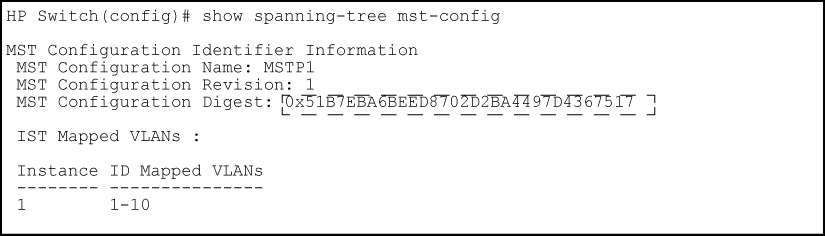
The Configuration Digest value shown in Mapping VLANs on other HP switches is not the same as in Mapping VLANs with the range option where all VLANs are included, indicating that these switches do not operate in the same instance.
The Common Spanning Tree (CST) will still have the correct root associations.
Before updating to a new version of software, follow these steps:
-
Enter the
show config filescommand to display your current configuration files:HP Switch(config)#: show config files Configuration files: id | act pri sec | name ---+-------------+-------------------- 1 | * * * | config1 2 | | config2 3 | |
-
To save a configuration file for software version K.12.43, enter this command:
HP Switch(config)#: copy config config1 config configK1243.cfg
Choose any name for the saved configuration file that you prefer.
-
Display the configuration files as shown in the following example. Note the newly created configuration file listed.
HP Switch(config)#: show config files

Configuration files:

 id | act pri sec | name
 ---+-------------+----------------------
  1 |  *   *   *  | config1
  2 |             | config2
  3 |             | configK1243.cfg
-
Update the switch to the desired version, for example, K.12.51. Enter the
show flashcommand to see the results. The switch is now running the software version K.12.51.HP Switch(config)#: show flash Image Size(Bytes) Date Version Build #: ----- ---------- -------- ------- ------- Primary Image : 6771179 04/17/08 K.12.51 304 Secondary Image : 7408949 11/06/08 K.12.43 123 Boot Rom Version: K.12.12 Default Boot : Primary
-
To run the prior software version (K.12.43 in this example), enter this command:
HP Switch(config)#: boot system flash secondary config configK1243.cfg
After rebooting, the switch is running software version K.12.43 and is using the configuration file that you saved for this software version, configK1243.cfg.
You can also save the K.12.43 configuration file on a TFTP server. To reload the K.12.43 version of the software again, reload the configuration file before doing the reload.
|
|
|
![[NOTE: ]](images/note.gif) |
NOTE: SNMP MIB Support for MSTP is a superset of the STP/802.1D and RSTP/802.1w protocols and uses the MIB objects defined for these two protocols. |
|
|
The following commands display the MSTP statistics for the connections between MST regions in a network.
Syntax:
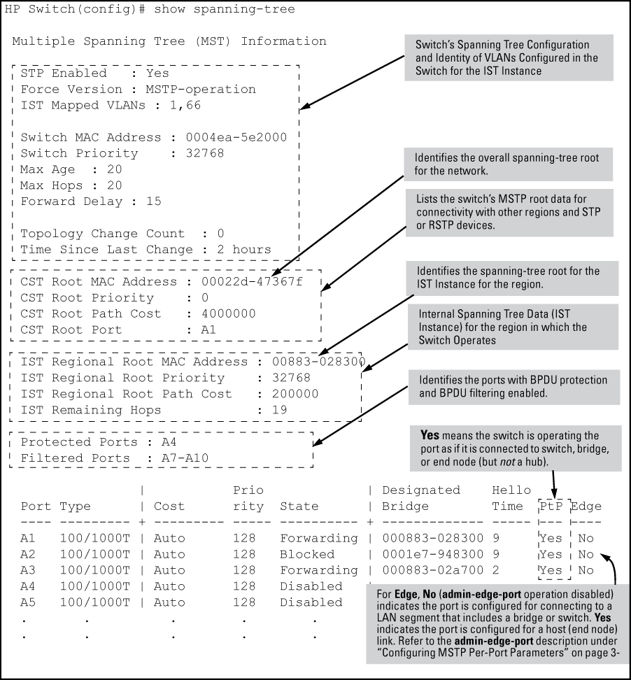
Displays the switch's global and regional spanning tree status, plus the per-port spanning tree operation at the regional level. Values for the following parameters appear only for ports connected to active devices:
Designated Bridge, Hello Time, PtP and Edge.
Syntax:
Displays the spanning tree status for the designated ports. You can list data for a series of ports and port trunks by specifying the first and last port or trunk of any consecutive series of ports and trunks. For example, to display data for port A20-A24 and trk1, you would use this command:
show spanning-tree a20-a42,trk1
The following commands display the MSTP statistics for the connections between MST regions in a network.
Syntax:
show spanning-tree detail
Syntax:
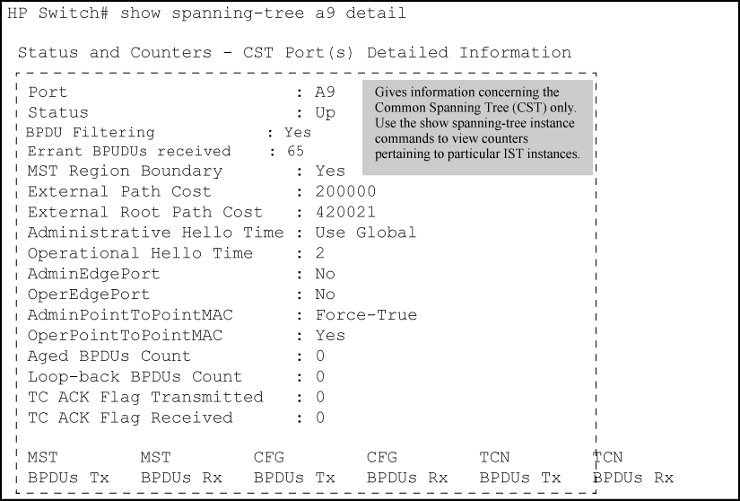
show spanning-tree <port-list> detail
|
|
|
|
|
NOTE: This command gives information about the CST only. To view details of specific MST instances, use the |
|
|
The following commands display the MSTP statistics for a specified MST instance.
Syntax:
Displays the MSTP statistics for either the IST instance or a numbered MST instance running on the switch.
Syntax:
Syntax:
Displaying status for a specific instance of an MSTP
This shows how to display detailed status for all active ports for a specific instance of MSTP.
HP Switch(config)#: show spanning-tree instance 11
 MST Instance Information
  Instance ID : 11
  Mapped VLANs : 111,300
  Switch Priority        : 32768

  Topology Change Count   : 2
  Time Since Last Change  : 4 mins

 Regional Root MAC Address : 1cc1de-cfbc80
 Regional Root Priority    : 32768
 Regional Root Path Cost   : 400000
 Regional Root Port        : This switch is root
 Remaining Hops            : 20

                                                          Designated
 Port  Type      Cost      Priority Role       State      Bridge
 ----- --------- --------- -------- ---------- ---------- -------------
 1     10/100TX  200000    128      Root       Forwarding 1cc1de-cfbc80
 2     10/100TX  200000    128      Designated Forwarding 1cc1de-02a700
 3     10/100TX  Auto      112      Designated Forwarding 1cc1de-02a700
 4     10/100TX  Auto      128      Disabled   Disabled
 .        .       .         .          .         .
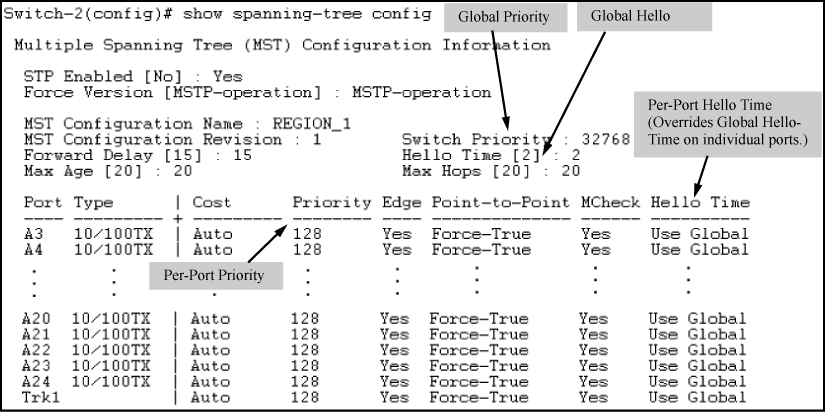
This command displays the switch's basic and MST region spanning tree configuration, including basic port connectivity settings.
Syntax:
show spanning-tree config
The upper part of this output shows the switch's global spanning tree configuration that applies to the MST region. The port listing shows the spanning tree port parameter settings for the spanning tree region operation configured by the
spanning-treecommand. For information on these parameters, see Configuring MSTP per-port parameters.<port-list>
Syntax:
show spanning-tree <port-list> config
This command shows the same data as the above command, but lists the spanning tree port parameter settings for only the specified port or trunk. You can list data for a series of ports and port trunks by specifying the first and last port or trunk of any consecutive series of ports and trunks. For example, to display data for port A20-A24 andtrk1, use the command:
show spanning-tree a20-a24,trk1 config
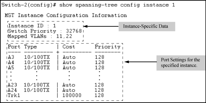
These commands display the per-instance port configuration and current state, along with instance identifiers and regional root data.
Syntax:
The upper part of this output shows the instance data for the ist or for the specified instance. The lower part of the output lists the spanning tree port settings for the specified instance.
Syntax:
This command is useful for quickly verifying the allocation of VLANs in the switch's MSTP configuration and for viewing the configured region identifiers.
Syntax:
show spanning-tree mst-config
NOTE: The switch computes the MSTP Configuration Digest from the VID to MSTI configuration mappings on the switch itself. As required by the 802.1s standard, all MSTP switches within the same region must have the same VID to MSTI assignments and any given VID can be assigned to either the IST or one of the MSTIs within the region. Thus, the MSTP Configuration Digest must be identical for all MSTP switches intended to belong to the same region. When comparing two MSTP switches, if their Digest identifiers do not match, they cannot be members of the same region. (See Displaying a region-level configuration.)
Displaying a region-level configuration
HP Switch(config)#: show spanning-tree net-config

 MST Configuration Identifier Information

  MST Configuration Name : REGION_1
  MST Configuration Revision : 1
  MST Configuration Digest : 0xDAD6A13EC5141980B7EBDA71D8991E7C

  IST Mapped VLANs : 1,66

  Instance ID Mapped VLANs
  -------- ---------------
  1        11,22
  2        33,44,55
This command displays the MSTP configuration the switch will implement if you execute the spanning tree pending apply command. See Enabling an entire MST region at once or exchanging one region configuration for another.
Syntax:
Displaying a pending configuration
HP Switch(config)#: show spanning-tree pending instance 3

 Pending MST Instance Configuration Information

  MST Configuration Name : New-Version_01
  MST Configuration Revision : 1
  Instance ID : 3
  Mapped VLANs : 3

Switch(config)#: show spanning-tree pending mst-config

 Pending MST Configuration Identifier Information

  MST Configuration Name : New-Version_01
  MST Configuration Revision : 1

  IST Mapped VLANs : 1,2,4-4094

  Instance ID Mapped VLANs
  ----------- ---------------------------------------
  3           3
Loop protection provides protection against loops by transmitting loop protocol packets out of ports on which loop protection has been enabled. When the switch sends out a loop protocol packet and then receives the same packet on a port that has a receiver-action of send-disable configured, it shuts down the port from which the packet was sent.
Syntax:
[no] loop-protect <port-list> [receiver-action [<send-disable> | <no-disable>] | transmit-interval <1-10> | disable-timer <0-604800> | trap loop-detected ] [mode] [port | vlan] [vlan <vid-list>]
Configures per-port loop protection on the switch.
-
Configure port mode with this command:
HP Switch(config)#: loop-protect mode port
-
Enter the
loop-protectcommand and specify the ports on which loop protection should be enabled. For example:HP Switch(config)#: loop-protect 1-2
-
Optionally specify
receiver-actionofsend-disableto shut down the port in the event of a loop. For example:HP Switch(config)#: loop-protect 1-2 receiver-action send-disable
VLANs can be configured for loop protection only when operating in VLAN mode. When loop-protect is enabled for a VLAN and a loop-protect enabled interface is a member of that VLAN, loop protect packets are sent on that VLAN to detect loops.
When changing from VLAN mode to port mode, the following prompt appears. The VLANs are then no longer configured for loop protection.
Syntax:
Displays the loop protection status for VLANs. If no ports are specified, the information is displayed only for ports with loop protection enabled.
Displaying loop protection information for port mode
HP Switch(config)#: show loop-protect 1-2

 Status and Counters - Loop Protection Information

 Transmit Interval (sec)    : 5
 Port Disable Timer (sec)   : 5
 Loop Detected Trap         : Enabled
 Loop Protect Mode          : port
 Loop Protect Enabled VLANs :


     Loop    Loop     Detected  Loop     Time Since  Rx           Port
Port Protect Detected on VLAN   Count    Last Loop   Action       Status
---- ------- -------- --------- -------- ----------- ----------   ---------
1    Yes     Yes                1        5s          send-disable Down
2    Yes     No                 0                    send-disable Up
Syntax:
Displays the loop protection status for VLANs. If no ports are specified, the information is displayed only for the ports that have loop protection enabled.
Displaying loop protection information for VLAN mode
HP Switch(config)#: show loop-protect 1-2

 Status and Counters - Loop Protection Information

 Transmit Interval (sec)   : 5
 Port Disable Timer (sec)  : 5
 Loop Detected Trap        : Enabled
 Loop Protect Mode         : Vlan
 Loop Protect Enabled VLANs : 20,30


      Loop   Loop     Detected  Loop     Time Since  Rx           Port
Port Protect Detected on VLAN   Count    Last Loop   Action       Status
---- ------- -------- --------- -------- ----------- ----------   ---------
1    Yes     Yes        20      1        45s         send-disable Down
2    Yes     No                 0                    send-disable Up
For more information, see Loop protection.
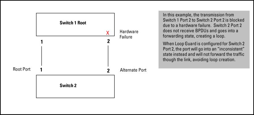
Spanning Tree (STP) is used to ensure a loop-free topology over the LAN. Occasionally a hardware or software failure can cause STP to fail, creating STP/forwarding loops that can cause network failures where unidirectional links are used. The non-designated port transitions in a faulty manner because the port is no longer receiving STP BPDUs.
STP Loop Guard causes the non-designated port to go into the STP loop inconsistent state instead of the forwarding state. In the loop-inconsistent state the port prevents data traffic and BPDU transmission through the link, therefore avoiding the loop creation. When BPDUs again are received on the inconsistent port, it resumes normal STP operation automatically. STP loop guard is best applied on blocking or forwarding ports.
Syntax:
Enables STP loop guard on a particular port or ports. The
noform of the command disables STP loop guard.
Enabling spanning tree loop guard on Port 2 and displaying the port's status
HP Switch(config)#: spanning-tree 2 loop-guard
HP Switch(config)#: show spanning-tree

 Multiple Spanning Tree (MST) Information

  STP Enabled   : Yes
  Force Version : MSTP-operation
  IST Mapped VLANs : 1-4094
  Switch MAC Address : 0024a8-d13a40
  Switch Priority    : 32768
  Max Age  : 20
  Max Hops : 20
  Forward Delay : 15

  Topology Change Count  : 1
  Time Since Last Change : 20 mins

  CST Root MAC Address : 001083-847000
  CST Root Priority    : 0
  CST Root Path Cost   : 60000
  CST Root Port        : 1

  IST Regional Root MAC Address : 0024a8-d13a40
  IST Regional Root Priority    : 32768
  IST Regional Root Path Cost   : 0
  IST Remaining Hops            : 20

  Root Guard Ports     :
  Loop Guard Ports     : 2
  TCN Guard Ports      :
  BPDU Protected Ports :
  BPDU Filtered Ports  :
  PVST Protected Ports :
  PVST Filtered Ports  :

                 |           Prio              | Designated    Hello
Port   Type      | Cost      rity State        | Bridge        Time PtP Edge
------ --------- + --------- ---- ------------ + ------------- ---- --- ----
1      100/1000T | 20000     128  Forwarding   | 001871-cdea00 2    Yes No
2      100/1000T | Auto      128  Inconsistent |
3      100/1000T | Auto      128  Disabled     |
4      100/1000T | Auto      128  Disabled     |
5      100/1000T | Auto      128  Disabled     |
6      100/1000T | Auto      128  Disabled     |
7      100/1000T | Auto      128  Disabled     |
8      100/1000T | Auto      128  Disabled     |
Displaying summary spanning tree configuration information
HP Switch(config)#: show spanning-tree config

 Multiple Spanning Tree (MST) Configuration Information

  STP Enabled [No] : Yes
  Force Version [MSTP-operation] : MSTP-operation
  Default Path Costs [802.1t] : 802.1t
  MST Configuration Name : 0024a8d13a40
  MST Configuration Revision : 0       Switch Priority : 32768
  Forward Delay [15] : 15              Hello Time [2] : 2
  Max Age [20] : 20                    Max Hops [20] : 20

               | Path      Prio Admin Auto Admin Hello  Root  Loop  TCN   BPDU
Port Type      | Cost      rity Edge  Edge PtP   Time   Guard Guard Guard Flt
---- --------- + --------- ---- ----- ---- ----- ------ ----- ----- ----- ---
1    100/1000T | Auto      128  No    Yes  True  Global No    No    No    No
2    100/1000T | Auto      128  No    Yes  True  Global No    Yes   No    No
3    100/1000T | Auto      128  No    Yes  True  Global No    No    No    No
4    100/1000T | Auto      128  No    Yes  True  Global No    No    No    No
5    100/1000T | Auto      128  No    Yes  True  Global No    No    No    No
6    100/1000T | Auto      128  No    Yes  True  Global No    No    No    No
.
.
.
Displaying detailed spanning tree configuration information
HP Switch(config)#: show spanning-tree detail

 Status and Counters - CST Port(s) Detailed Information
  Port                     : 1
  Status                   : Up
.
.
.

  Port                     : 2
  Status                   : Up
  BPDU Protection          : No
  BPDU Filtering           : No
  PVST Protection          : No
  PVST Filtering           : No
  Errant BPDU Count        : 0
  Root Guard               : No
  Loop Guard               : Yes
  TCN Guard                : No
  MST Region Boundary      : Yes
  External Path Cost       : 20000
  External Root Path Cost  : 40000
  Administrative Hello Time: Global
  Operational Hello Time   : 2
  AdminEdgePort            : No
  Auto Edge Port           : Yes
  OperEdgePort             : No
  AdminPointToPointMAC     : True
  OperPointToPointMAC      : Yes
  Aged BPDUs Count         : 0
  Loop-back BPDUs Count    : 0
  TC ACK Flag Transmitted  : 0
  TC ACK Flag Received     : 1

 MST        MST        CFG        CFG        TCN        TCN
 BPDUs Tx   BPDUs Rx   BPDUs Tx   BPDUs Rx   BPDUs Tx   BPDUs Rx
 ---------- ---------- ---------- ---------- ---------- ----------
 3          0          24354      1682       0          13
Displaying spanning tree configuration information for a single port
HP Switch(config)#: show spanning-tree 2

 Multiple Spanning Tree (MST) Information

  STP Enabled   : Yes
  Force Version : MSTP-operation
  IST Mapped VLANs : 1-4094
  Switch MAC Address : 0024a8-d13a40
  Switch Priority   : 32768
  Max Age : 20
  Max Hops : 20
  Forward Delay : 15

  Topology Change Count  : 1
  Time Since Last Change : 58 mins

  CST Root MAC Address : 001083-847000
  CST Root Priority   : 0
  CST Root Path Cost  : 60000
  CST Root Port       : 1

  IST Regional Root MAC Address : 0024a8-d13a40
  IST Regional Root Priority   : 32768
  IST Regional Root Path Cost  : 0
  IST Remaining Hops           : 20

  Root Guard Ports     :
  Loop Guard Ports     : 2
  TCN Guard Ports      :
  BPDU Protected Ports :
  BPDU Filtered Ports  :
  PVST Protected Ports :
  PVST Filtered Ports  :

                 |           Prio              | Designated    Hello
Port   Type      | Cost      rity State        | Bridge        Time PtP Edge
------ --------- + --------- ---- ------------ + ------------- ---- --- ----
2      100/1000T | Auto      128  Inconsistent |
This section describes the show spanning-tree commands to use to monitor, troubleshoot and debug the operation of a multiple-instance spanning tree configuration in a network.
The show spanning-tree commands described in this section allow for focusing on increasingly specific levels of operation. For example, you can display debug information for:
-
All MST instances
-
All ports used in one MST instance
-
A specific port or several ports used in one MST instance
Also, you can display the change history for the root (bridge) switch used as the single forwarding path for:
-
All MST regions, STP bridges and RSTP bridges in an STP network
-
All VLANs on MSTP switches in a region
-
All VLANs on MSTP switches in an mst instance
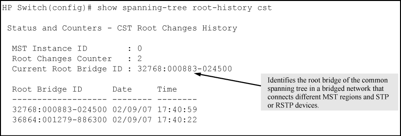
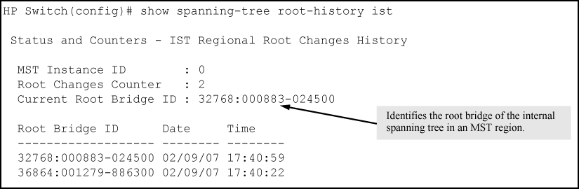
The show spanning-tree root-history command lets you display change history information (up to 10 history entries) for a specified root bridge in any of the following MSTP topologies:
-
Common Spanning Tree (
cst):Provides connectivity in a bridged network between MST regions, STP LANs and RSTP LANs.
-
Internal Spanning Tree (
ist):Provides connectivity within an MST region for VLANs associated with the default Common and Internal Spanning Tree (CIST) instance in your network (VLANs that have not been mapped to an MST instance).
-
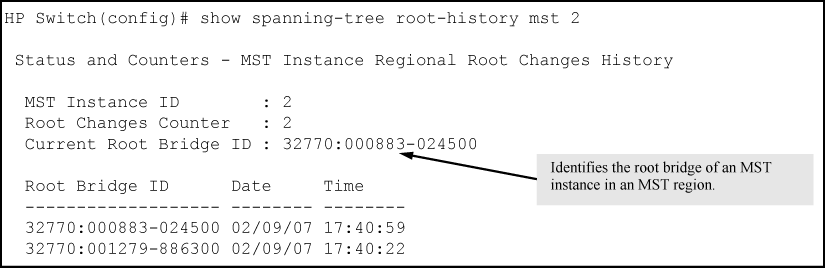
MST Instance (
mst):Connects all static and dynamic VLANs assigned to a multiple spanning tree instance.
Syntax:
show spanning tree root-history [ <cst | ist | mst ] <instance-id> >
Displays the change history for the root bridge in the specified MSTP topology.
Displays the change history for the root bridge of a spanning tree network, including MST regions and STP and RSTP bridges.
Displays the change history for the root bridge in the IST instance of an MST region.
Displays the change history for the root bridge in an MST instance, where
<instance-id>is an ID number from 1 to 16.
Use the show spanning-tree root-history command to view the number and dates of changes in the assignment of a root bridge. Possible intrusion into your MST network may occur if an unauthorized external device gains access to a spanning tree by posing as the root device in a topology. To prevent an MST port connected to the device from being selected as the root port in a topology, use the spanning-tree root-guard command.
Sample output of the show spanning-tree root-history command for different MSTP topologies
The following examples show sample output of the show spanning-tree root-history command for different MSTP topologies. In each example, the root bridge ID is displayed in the format: <priority>: <mac-address>
-
<priority>is the MSTP switch priority calculated for one of the following:-
The IST (regional) root switch using the
spanning-tree prioritycommand -
An MSTI root switch using the
spanning-tree instance prioritycommand
-
-
<mac-address>is the MAC address of the root (bridge) switch.
The show spanning-tree debug-counters command allows you to display the aggregate values of all MSTP debug counters that are maintained on a switch. These aggregate values are a summary of the information collected from all ports and from all spanning tree instances that forward traffic on switch ports.
Use the displayed diagnostic information to globally monitor MSTP operation on a per-switch basis.
Syntax:
show spanning-tree debug-counters
Displays debug counters for MSTP activity on all ports configured for VLANs used in spanning tree instances.
Displaying output for debug counters
The following example shows sample output of the show spanning-tree debug-counters command for all ports.
HP Switch(config)#: show spanning-tree debug-counters

 Status and Counters - MSTP Bridge Common Debug Counters Information

  Counter Name                      Aggregated Value Collected From
  --------------------------------- ---------------- --------------
  Invalid BPDUs                     0                CIST
  Errant BPDUs                      170927           CIST
  MST Config Error BPDUs            0                CIST
  Looped-back BPDUs                 0                CIST
  Starved BPDUs/MSTI MSGs           0                CIST/MSTIs
  Exceeded Max Age BPDUs            0                CIST
  Exceeded Max Hops BPDUs/MSTI MSGs 0                CIST/MSTIs
  Topology Changes Detected         2                CIST/MSTIs
  Topology Changes Tx               6                CIST/MSTIs
  Topology Changes Rx               4                CIST/MSTIs
  Topology Change ACKs Tx           0                CIST
  Topology Change ACKs Rx           0                CIST
  TCN BPDUs Tx                      0                CIST
  TCN BPDUs Rx                      0                CIST
  CFG BPDUs Tx                      0                CIST
  CFG BPDUs Rx                      0                CIST
  RST BPDUs Tx                      0                CIST
  RST BPDUs Rx                      0                CIST
  MST BPDUs/MSTI MSGs Tx            10               CIST/MSTIs
  MST BPDUs/MSTI MSGs Rx            341802           CIST/MSTIs
The show spanning-tree debug-counters instance command lets you display the aggregate values of all MSTP debug counters maintained on a switch for a specified spanning tree instance. These aggregate values are a summary of information collected from all ports that have VLANs assigned to the specified instance.
Use this command to troubleshoot the global MSTP diagnostic information displayed in show spanning-tree debug-counters command output when you suspect unauthorized MSTP activity in a specific MST instance.
Syntax:
show spanning-tree debug-counters instance <instance-id>
Displays debug counters for MSTP activity on all ports configured for VLANs in the specified MST instance.
The valid values for
instance<instance-id>are 0 to 16, where 0 specifies the default MST (CIST) instance and 1 to 16 specify a multiple spanning tree (MST) instance.
Displaying debug counters for a CIST instance
The following example shows sample output of the show spanning-tree debug-counters instance command when applied to the Common and Internal Spanning Tree (CIST) instance (default MST instance 0) in the network.
HP Switch(config)#: show spanning-tree debug-counters instance 0

 Status and Counters - CIST Common Debug Counters Information

  MST Instance ID : 0

  Counter Name                      Aggregated Value Collected From
  --------------------------------- ---------------- --------------
  Invalid BPDUs                     0                Ports
  Errant BPDUs                      172603           Ports
  MST Config Error BPDUs            0                Ports
  Looped-back BPDUs                 0                Ports
  Starved BPDUs                     0                Ports
  Exceeded Max Age BPDUs            0                Ports
  Exceeded Max Hops BPDUs           0                Ports
  Topology Changes Detected         1                Ports
  Topology Changes Tx               3                Ports
  Topology Changes Rx               2                Ports
  Topology Change ACKs Tx           0                Ports
  Topology Change ACKs Rx           0                Ports
  TCN BPDUs Tx                      0                Ports
  TCN BPDUs Rx                      0                Ports
  CFG BPDUs Tx                      0                Ports
  CFG BPDUs Rx                      0                Ports
  RST BPDUs Tx                      0                Ports
  RST BPDUs Rx                      0                Ports
  MST BPDUs Tx                      5                Ports
  MST BPDUs Rx                      172577           Ports
The show spanning-tree debug-counters instance ports command displays the aggregate values of all MSTP debug counters maintained on one or more ports used by a specified spanning tree instance. These aggregate values are a summary of information collected from the specified ports that have VLANs assigned to the specified instance.
Use this command to troubleshoot at a finer level the more general MSTP diagnostic information displayed in the show spanning-tree debug-counters instance command output, when you suspect unauthorized MSTP activity on one or more MST ports in an MST instance.
Syntax:
show spanning-tree debug-counters instance <instance-id> ports <port-list>
Displays debug counters for MSTP activity on the specified ports configured for VLANs in the specified MST instance.
The valid values for
<instance-id>are from 0 to 16, where 0 specifies the default MST (CIST) instance and 1 to 16 specify an MST instance.Specifies one or more MST ports or trunk ports. In the port list, enter a series of ports by separating the first and last ports in the series with a dash (-); for example,
a2-a8ortrk1-trk3. Separate individual ports and series of ports with a comma; for example,a2-a8, a20, trk1, trk4-trk5.
Displaying debug counters for a CIST and MST instance
The following example shows sample output of the show spanning-tree debug-counters instance ports command for both the CIST (default MST instance 0) and an MST instance (instance 2) on port A15.
HP Switch(config)#: show spanning-tree debug-counters instance 0 ports a15

 Status and Counters - CIST Port(s) Debug Counters Information

  MST Instance ID : 0
  Port : A15

  Counter Name                Value      Last Updated
  --------------------------- ---------- -----------------
  Invalid BPDUs               0
  Errant BPDUs                0
  MST Config Error BPDUs      0
  Looped-back BPDUs           0
  Starved BPDUs               0
  Exceeded Max Age BPDUs      0
  Exceeded Max Hops BPDUs     0
  Topology Changes Detected   1         02/09/07 17:40:59
  Topology Changes Tx         3         02/09/07 17:41:03
  Topology Changes Rx         2         02/09/07 17:41:01
  Topology Change ACKs Tx     0
  Topology Change ACKs Rx     0
  TCN BPDUs Tx                0
  TCN BPDUs Rx                0
  CFG BPDUs Tx                0
  CFG BPDUs Rx                0
  RST BPDUs Tx                0
  RST BPDUs Rx                0
  MST BPDUs Tx                5         02/09/07 17:41:03
  MST BPDUs Rx                173540    02/13/07 18:05:34
Displaying debug counters output for one port in an MST instance
The following example shows spanning tree debug-counters instance ports command output for one port in an MST instance.
HP Switch(config)#: show spanning-tree debug-counters instance 2 ports a15

 Status and Counters - MSTI Port(s) Debug Counters Information

   MST Instance ID : 2
   Port : A15

   Counter Name                Value      Last Updated
   --------------------------- ---------- -----------------
   Starved MSTI MSGs           0
   Exceeded Max Hops MSTI MSGs 0
   Topology Changes Detected   1          02/09/07 17:40:59
   Topology Changes Tx         3          02/09/07 17:41:03
   Topology Changes Rx         2          02/09/07 17:41:01
   MSTI MSGs Tx                5          02/09/07 17:41:03
   MSTI MSGs Rx                173489     02/13/07 18:03:52
The following table contains descriptions of the debugging information displayed in the output of show spanning-tree debug-counters commands.
MSTP debug command output: field descriptions
| Field | Displays the number of... |
|---|---|
Invalid BPDUs |
Received BPDUs that failed standard MSTP (802.1Q-REV/D5.0 14.4) validation checks and were dropped. This counter is maintained by the CIST (default MST instance 0) on a per-port basis. |
Errant BPDUs |
Received BPDUs that were dropped on a port that is configured to not expect BPDU packets. This counter is maintained by the CIST (MST instance, 0default MST instance 0 in the network) on a per-port basis and is incremented each time a BPDU packet is received on a port configured with the BPDU filter to ignore incoming BPDU packets (spanning-tree bpdu-filter command) or the BPDU protection feature to disable the port when BPDU packets are received (spanning-tree bpdu-protection command). |
MST Config Error BPDUs |
BPDUs received from a neighbor bridge with inconsistent MST configuration information. For example, BPDUs from a transmitting bridge may contain the same MST configuration identifiers (region name and revision number) and format selector as the receiving bridge, but the value of the Configuration Digest field (VLAN ID assignments to regional IST and MST instances) is different. This difference indicates a probable configuration error in MST region settings on the communicating bridges. The received BPDU is still processed by MSTP. This counter is maintained by the CIST (default MST instance 0) on a per-port basis. |
Looped-back BPDUs |
Times a port has received self-sent BPDU packets as the result of an external loop condition in which the BPDUs were looped back to the originating transmission port. The received BPDU is still processed by MSTP and the port changes to a blocked state. This counter is maintained by the CIST (default MST instance 0) on a per-port basis. |
Starved BPDUs |
Times that no BPDUs are received within the scheduled interval (three times the Hello Time value configured with the This counter is maintained by the CIST (default MST instance 0) on a per-port basis. |
Starved MSTI MSGs |
Times that no BPDUs are received within the scheduled interval (three times the Hello Time value configured with the This counter is maintained by the CIST (default MST instance 0) on a per-port basis. |
Exceeded Max Age BPDUs |
Times that a BPDU packet is received from a bridge external to the MST region with a Message Age value greater than the configured value of the Max Age parameter ( This counter is maintained by the CIST (default MST instance 0) on a per-port basis. |
Exceeded Max Hops BPDUs |
Times that a BPDU packet is received from a bridge internal to the MST region with a CIST Remaining Hops value less than or equal to 1. This may occur if the receiving bridge is located too far from the CIST regional root bridge (beyond the configured size of the MST region on the CIST regional root bridge) or if a BPDU packet with invalid CIST regional root bridge information is continuously circulating between bridges in the MST Region and needs to be aged out. This counter is maintained by the CIST (default MST instance 0 in the region) on a per-port basis. |
Exceeded Max Hops MSTI MSGs |
Times that an MSTI MSG packet is received from a bridge internal to the MST region with an MSTI Remaining Hops value less than or equal to 1. This may occur if the receiving bridge is located too far from the MSTI regional root bridge (beyond the configured size of the MST region on the MSTI regional root bridge) or if a BPDU packet with invalid MSTI regional root bridge information is continuously circulating between bridges in an MST region and needs to be aged out. This counter is maintained on a per-MSTI per-port basis. |
Topology Changes Detected |
Times that a Topology Change event is detected by the CIST or MSTI port and the port triggers a topology change propagation throughout the network. A Topology Change event occurs when a non-edge port enters forwarding state. This counter is maintained on a per-CIST per-port and on a per-MSTI per-port basis. |
Topology Changes Tx |
Times that Topology Change information is propagated (sent out) through the port to the rest of the network. For a CIST port, the counter is the number of times that a CFG, RST or MST BPDU with the TC flag set is transmitted out of the port. For an MSTI port, the counter is the number of times that a MSTI configuration message with the TC flag set is transmitted out of the port. This counter is maintained on a per-CIST per-port and on a per-MSTI per-port bases. |
Topology Changes Rx |
Times that Topology Change information is received from the peer port. For a CIST port, the counter is the number of times that a CFG, RST or MST BPDU with the TC flag set is received. For an MSTI port, the counter is the number of times that an MSTI configuration message with the TC flag set is received. This counter is maintained on a per-CIST per-port and on a per-MSTI per-port basis. |
Topology Change ACKs Tx |
Times that the Topology Change acknowledgement is transmitted through the port (number of CFG, RST or MST BPDUs transmitted with the Topology Change Acknowledge flag set). This counter is maintained by the CIST (default MST instance 0) on a per-port basis. |
Topology Change ACKs Rx |
Times the Topology Change acknowledgement is received on the port (number of CFG, RST or MST BPDUs received with the Topology Change Acknowledge flag set). This counter is maintained by the CIST (default MST instance 0) on a per-port basis. |
TCN BPDUs Tx |
Topology Change Notification BPDUs that are transmitted through the port. This counter is maintained by the CIST (default MST instance 0) on a per-port basis. |
TCN BPDUs Rx |
Topology Change Notification BPDUs that are received on the port. This counter is maintained by the CIST (default MST instance 0) on a per-port basis. |
CFG BPDUs Tx |
802.1D Configuration BPDUs that are transmitted through the port. This counter is maintained by the CIST (default MST instance 0) on a per-port basis. |
CFG BPDUs Rx |
802.1D Configuration BPDUs that are received on the port. This counter maintained by the CIST (default MST instance 0) on a per-port basis. |
RST BPDUs Tx |
802.1w RST BPDUs that are transmitted through the port. This counter is maintained by the CIST (default MST instance 0) on a per-port basis. |
RST BPDUs Rx |
802.1w RST BPDUs that are received on the port. This counter is maintained by the CIST (default MST instance 0) on a per-port basis. |
MST BPDUs Tx |
802.1s MST BPDUs that are transmitted through the port. This counter is maintained by the CIST (default MST instance 0) on a per-port basis. |
MST BPDUs Rx |
802.1s MST BPDUs that are received on the port. This counter is maintained by the CIST (default MST instance 0) on a per-port basis. |
MSTI MSGs Tx |
Times that a configuration message for a specific MSTI was encoded in (802.1s) MST BPDUs that are transmitted through the port. This counter is maintained on a per-MSTI per-port basis. |
MSTI MSGs Rx |
Times that the MSTI detected a configuration message destined to the MSTI in (802.1s) MST BPDUs received on the port. This counter is maintained on a per-MSTI per-port basis. |
Troubleshooting MSTP operation
| Problem | Possible cause |
|---|---|
| Duplicate packets on a VLAN, or packets not arriving on a LAN at all. | The allocation of VLANs to MSTIs may not be identical among all switches in a region. |
| A switch intended to operate in a region does not receive traffic from other switches in the region. |
An MSTP switch intended for a particular region may not have the same configuration name or region revision number as the other switches intended for the same region. The MSTP configuration name ( Another possible cause is that the set of VLANs and VLAN ID-to-MSTI mappings ( |
|
|
|
|
|
NOTE: For information on configuring RPVST+, see the Rapid per-VLAN spanning tree operation chapter in this guide. |
|
|
Without spanning tree, having more than one active path between a pair of nodes causes loops in the network, which can result in duplication of messages leading to a "broadcast storm" that can bring down the network.
|
|
|
|
|
NOTE: MSTP cannot protect against loops when there is an unmanaged device on the network that drops spanning tree packets, or may fail to detect loops where this is an edge port configured with client authentication (802.1X, Web and MAC authentication). To protect against the formation of loops in these cases, you can use the loop protection feature (see Configuring loop protection). |
|
|
Multiple-Instance spanning tree operation (802.1s) ensures that only one active path exists between any two nodes in a spanning tree instance. A spanning tree instance comprises a unique set of VLANs and belongs to a specific spanning tree region. A region can comprise multiple spanning tree instances (each with a different set of VLANs) and allows one active path among regions in a network. Applying VLAN tagging to the ports in a multiple-instance spanning tree network enables blocking of redundant links in one instance while allowing forwarding over the same links for non-redundant use by another instance.
VLAN/Instance groupings
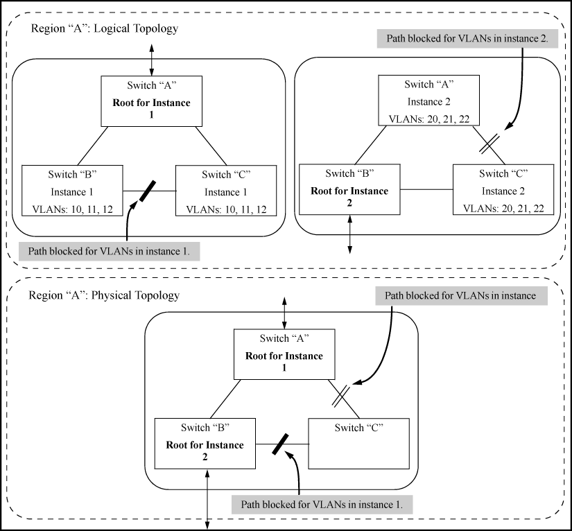
Suppose there are three switches in a region configured with VLANs grouped into two instances, as follows:
| VLANs | Instance 1 | Instance 2 |
|---|---|---|
| 10, 11, 12 | Yes | No |
| 20, 21, 22 | No | Yes |
The logical and physical topologies resulting from these VLAN/Instance groupings result in blocking on different links for different VLANs:
MSTP maps active, separate paths through separate spanning tree instances and between MST regions. Each MST region comprises one or more MSTP switches. Note that MSTP recognizes an STP or RSTP LAN as a distinct spanning tree region.
In the factory default configuration, spanning tree operation is off. Also, the switch retains its currently configured spanning tree parameter settings when disabled. Thus, if you disable spanning tree, then later re-enable it, the parameter settings will be the same as before spanning tree was disabled. The switch also includes a "Pending"feature that enables you to exchange MSTP configurations with a single command. (See Enabling an entire MST region at once or exchanging one region configuration for another.)
|
|
|
|
|
NOTE: The switch automatically senses port identity and type and automatically defines spanning tree parameters for each type, as well as parameters that apply across the switch. Although these parameters can be adjusted, HP strongly recommends leaving these settings in their default configurations unless the proposed changes have been supplied by an experienced network administrator who has a strong understanding of the IEEE 802.1D/w/s standards and operation. |
|
|
The switches covered in this guide use the IEEE 802.1s Multiple Spanning Tree Protocol (MSTP) standard.
The 802.1D and 802.1w spanning tree protocols operate without regard to a network's VLAN configuration and maintain one common spanning tree throughout a bridged network. Thus, these protocols map one loop-free, logical topology on a given physical topology. The 802.1s Multiple Spanning Tree protocol (MSTP) uses VLANs to create multiple spanning trees in a network, which significantly improves network resource utilization while maintaining a loop-free environment.
While the per-VLAN spanning tree approach adopted by some vendors overcomes the network utilization problems inherent in using STP or RSTP, using a per-VLAN technology with multiple VLANs can overload the switch's CPU. MSTP on the switches covered in this guide complies with the IEEE 802.1s standard and extends STP and RSTP functionality to map multiple independent spanning tree instances onto a physical topology. With MSTP, each spanning tree instance can include one or more VLANs and applies a separate, per-instance forwarding topology. Thus, where a port belongs to multiple VLANs, it may be dynamically blocked in one spanning tree instance, but forwarding in another instance. This achieves load-balancing across the network while keeping the switch's CPU load at a moderate level (by aggregating multiple VLANs in a single spanning tree instance). MSTP provides fault tolerance through rapid, automatic reconfiguration if there is a failure in a network's physical topology.
With MSTP-capable switches, you can create a number of MST regions containing multiple spanning tree instances. This requires the configuration of a number of MSTP-capable switches. However, it is not necessary to do this. You can just enable MSTP on an MSTP-capable switch and a spanning tree instance is created automatically. This instance always exists by default when spanning tree is enabled and is the spanning tree instance that communicates with STP and RSTP environments. The MSTP configuration commands operate exactly like RSTP commands and MSTP is backward-compatible with the RSTP-enabled and STP-enabled switches in your network.
|
|
|
|
|
CAUTION: Spanning tree interprets a switch mesh as a single link. Because the switch automatically gives faster links a higher priority, the default MSTP parameter settings are usually adequate for spanning tree operation. Because incorrect MSTP settings can adversely affect network performance, do not change the MSTP settings from their default values unless you have a strong understanding of how spanning tree operates. |
|
|
In a mesh environment, the default MSTP timer settings (Hello Time and Forward Delay) are usually adequate for MSTP operation. Because a packet crossing a mesh may traverse several links within the mesh, using smaller-than-default settings for the MSTP Hello Time and Forward Delay timers can cause unnecessary topology changes and end-node connectivity problems.
For MSTP information beyond what is provided in this manual, see the IEEE 802.1s standard.
All MSTP switches in a given region must be configured with the same VLANs and each MSTP switch within the same region must have the same VLAN-to-instance assignments. In addition, a VLAN can belong to only one instance within any region. Within a region:
-
All of the VLANs belonging to a given instance compose a single, active spanning tree topology for that instance.
-
Each instance operates independently of other regions.
Between regions there is a single, active spanning tree topology.
Assigning different groups of VLANs to different instances ensures that those VLAN groups use independent forwarding paths. For example, in Active topologies built by three independent MST instances each instance has a different forwarding path.
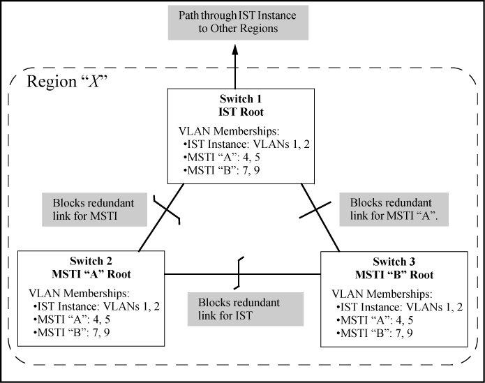
While allowing only one active path through a given instance, MSTP retains any redundant physical paths in the instance to serve as backups (blocked) paths in case the existing active path fails. Thus, if an active path in an instance fails, MSTP automatically activates (unblocks) an available backup to serve as the newactive path through the instance for as long as the original active path is down. Note also that a given port may simultaneously operate in different states (forwarding or blocking) for different spanning tree instances within the same region. This depends on the VLAN memberships to which the port is assigned. For example, if a port belongs to VLAN 1 in the IST instance of a region and also belongs to VLAN 4 in MSTI "x" in the same region, the port may apply different states to traffic for these two different instances.
Within a region, traffic routed between VLANs in separate instances can take only one physical path. To ensure that traffic in all VLANs within a region can travel between regions, all of the boundary ports for each region should belong to all VLANs configured in the region. Otherwise, traffic from some areas within a region could beblocked from moving to other regions.
All MSTP switches (as well as STP and RSTP switches) in a network use BPDUs (Bridge Protocol Data Units) to exchange information from which to build multiple, active topologies in the individual instances within a region and between regions. From this information:
-
The MSTP switches in each LAN segment determine a designated bridge and designated port or trunk for the segment.
-
The MSTP switches belonging to a particular instance determine the root bridge and root port or trunk for the instance.
-
For the IST instance within a region, the MSTP switches linking that region to other regions (or to STP or RSTP switches) determine the IST root bridge and IST root port or trunk for the region. (For any Multiple spanning tree instance—MSTI—in a region, the regional root may be a different switch that is not necessarily connected to another region.)
-
The MSTP switches block redundant links within each LAN segment, across all instances and between regions, to prevent any traffic loops.
As a result, each individual instance (spanning tree) within a region determines its regional root bridge, designated bridges and designated ports or trunks.
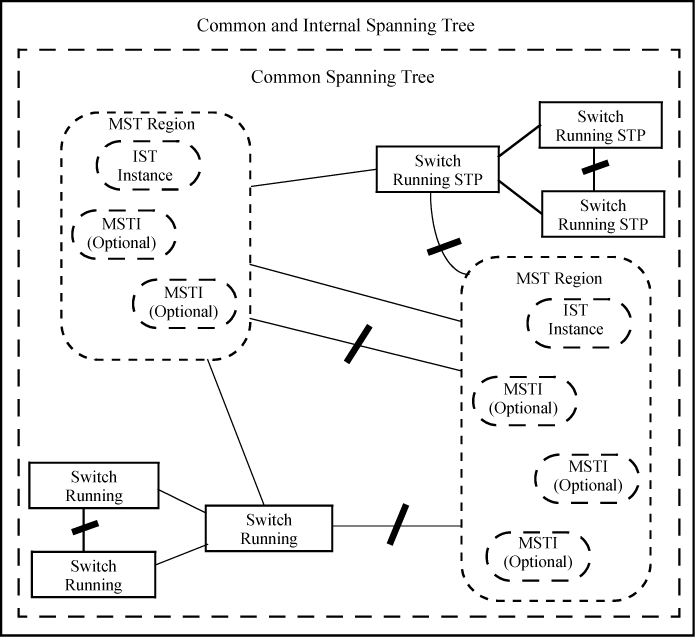
The IST instance and any MST instances in a region exist only within that region. Where a link crosses a boundary between regions (or between a region and a legacy STP or RSTP switch), traffic is forwarded or blocked as determined by the Common Spanning Tree (CST). The CST ensures that there is only one active path between any two regions, or between a region and a switch running STP and RSTP. (See An MSTP network with legacy STP and RSTP devices connected.)
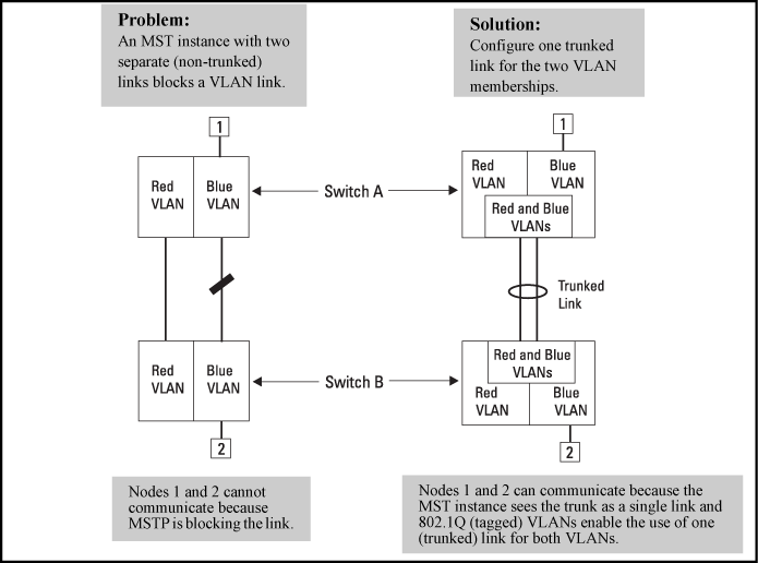
As indicated in the preceding sections, within a given MST instance, a single spanning tree is configured for all VLANs included in that instance. Thus if redundant physical links exist in separate VLANs within the same instance, MSTP blocks all but one of those links. However, you can prevent the bandwidth loss caused by blocked redundant links for different VLANs in an instance by using a port trunk. The following example shows how you can use a port trunk with 802.1Q (tagged) VLANs and MSTP without unnecessarily blocking any links or losing any bandwidth.
|
|
|
|
|
NOTE: All switches in a region should be configured with the VLANs used in that region and all ports linking MSTP switches together should be members of all VLANs in the region. Otherwise, the path to the root for a given VLAN will be broken if MSTP selects a spanning tree through a link that does not include that VLAN. |
|
|
A multiple spanning tree network comprises separate spanning tree instances existing in an MST region. (There can be multiple regions in a network.) Each instance defines a single forwarding topology for an exclusive set of VLANs. By contrast, an STP or RSTP network has only one spanning tree instance for the entire network and includes all VLANs in the network. (An STP or RSTP network operates as a single-instance network.) A region can include two types of STP instances:
-
Internal spanning tree Instance (IST Instance)
This is the default spanning tree instance in any MST region. It provides the root switch for the region and comprises all VLANs configured on the switches in the region that are not specifically assigned to Multiple Spanning Tree Instances (MSTIs, described below).
Within a region, the IST instance provides a loop-free forwarding path for all VLANs associated with it. VLANs that are not associated with an MSTI are, by default, associated with the IST instance. Note that the switch automatically places dynamic VLANs (resulting from GVRP operation) in the IST instance. Dynamic VLANs cannot exist in an MSTI (described below).
-
Multiple Spanning Tree Instance (MSTI)
This type of configurable spanning tree instance comprises all static VLANs you specifically assign to it and must include at least one VLAN. The VLANs you assign to an MSTI must initially exist in the IST instance of the same MST region. When you assign a static VLAN to an MSTI, the switch removes the VLAN from the IST instance. (Thus, you can assign a VLAN to only one MSTI in a given region.) All VLANs in an MSTI operate as part of the same single spanning tree topology. (The switch does not allow dynamic VLANs in an MSTI.)
|
|
|
|
|
CAUTION: When you enable MSTP on the switch, the default MSTP spanning tree configuration settings comply with the values recommended in the IEEE 802.1s Multiple Spanning Tree Protocol (MSTP) standard. Inappropriate changes to these settings can result in severely degraded network performance. For this reason, HP strongly recommends that changing these default settings be reserved only for experienced network administrators who have a strong understanding of the IEEE 802.1D/w/s standards and operation. |
|
|
-
All switches in a region must be configured with the same set of VLANs, as well as the same MST configuration name and MST configuration number.
-
Within a region, a VLAN can be allocated to either a single MSTI or to the region's IST instance.
-
All switches in a region must have the same VID-to-MST instance assignment.
-
There is one root MST switch per configured MST instance.
-
Because boundary ports provide the VLAN connectivity between regions, all boundary ports on a region's root switch should be configured as members of all static VLANs defined in the region.
-
There is one root switch for the Common and Internal Spanning Tree (CIST). At any given time, all switches in the network will use the per-port
hello-timeparameter assignments configured on the CIST root switch. -
Where multiple MST regions exist in a network, there is only one active, physical communication path between any two regions, or between an MST region and an STP or RSTP switch. MSTP blocks any other physical paths as long as the currently active path remains in service.
-
Within a network, an MST region appears as a virtual RSTP bridge to other spanning tree entities (other MST regions and any switches running 802.1D or 802.1w spanning tree protocols).
-
Within an MSTI, there is one physical communication path between any two nodes, regardless of how many VLANs belong to the MSTI. Within an IST instance, there is also one spanning tree across all VLANs belonging to the IST instance.
-
An MSTI comprises a unique set of VLANs and forms a single spanning tree instance within the region to which it belongs.
-
A dynamic VLAN learned by GVRP will always be placed in the IST instance and cannot be moved to any configured MST instance.
Dynamically learned GVRP VLANs can be mapped to MSTIs and support MSTP load balancing.
-
You can preconfigure static and dynamic VLAN ID-to-MSTI mappings before the VLAN is created on the switch. Later, when the static VLAN ID is configured or a dynamic GVRP VLAN is learned, the VLAN is automatically associated with the preconfigured MSTI. For more information, see Configuring MST instance parameters.
-
Communication between MST regions uses a single spanning tree.
-
If a port on a switch configured for MSTP receives a legacy (STP/802.1D or RSTP/802.1w) BPDU, it automatically operates as a legacy port. In this case, the MSTP switch interoperates with the connected STP or RSTP switch as a separate MST region.
-
Within an MST region, there is one logical forwarding topology per instance and each instance comprises a unique set of VLANs. Where multiple paths exist between a pair of nodes using VLANs belonging to the same instance, all but one of those paths will be blocked for that instance. However, if there are different paths in different instances, all such paths are available for traffic. Separate forwarding paths exist through separate spanning tree instances.
-
A port can have different states (forwarding or blocking) for different instances (which represent different forwarding paths).
-
MSTP interprets a switch mesh as a single link.
-
Configuring MSTP on the switch automatically configures the Internal Spanning Tree (IST) instance and places all statically and dynamically configured VLANs on the switch into the IST instance. The spanning tree instance vlan command creates a new MST instance and moves the VLANs you specify from the IST to the MSTI.
You must map a least one VLAN ID to an MSTI when you create it. You cannot map a VLAN ID to more than one instance. You can create up to 16 MSTIs in a region.
-
The
noform of the spanning tree instance vlan command removes one or more VLANs from the specified MSTI. If no VLANs are specified, thenoform of the command deletes the specified MSTI.When you remove a VLAN from an MSTI, the VLAN returns to the IST instance, where it can remain or be reassigned to another MSTI configured in the region.
-
If you enter the spanning tree instance vlan command before a static or dynamic VLAN is configured on the switch to preconfigure VLAN ID-to-MSTI mappings, no error message is displayed. Later, each newly configured VLAN that has already been associated with an MSTI is automatically assigned to the MSTI.
This new default behavior differs from automatically including configured (static and dynamic) VLANs in the IST instance and requiring you to manually assign individual static VLANs to an MSTI.
-
Valid VLAN IDs that you can map to a specified MSTI are numbered from 1 to 4094. The VLAN ID-to-MSTI mapping does not require a VLAN to be already configured on the switch. The MSTP VLAN enhancement lets you preconfigure MSTP topologies before the VLAN IDs associated with each instance exist on a switch.
-
When you use preconfigured VLAN ID-to-MSTI topologies, ensure that MSTP switches remain in the same region by mapping all VLAN IDs used in the region to the same MSTIs on each regional switch.
-
The existing MSTP topology configuration is automatically saved. All existing VLAN ID-to-MSTI assignments are maintained on a switch for uninterrupted MSTP network operation.
IEEE 802.1s MSTP includes RSTP functionality and is designed to be compatible with both IEEE 802.1D and 802.1w spanning tree protocols. Using the default configuration values, your switches will interoperate effectively with RSTP and STP devices. MSTP automatically detects when the switch ports are connected to non-MSTP devices in the spanning tree and communicates with those devices using 802.1D or 802.1w STP BPDU packets, as appropriate.
To enable effective interoperation with STP (802.1D) configured devices, however, you may need to adjust the default configuration values. Here are two such examples:
-
The rapid state transitions employed by MSTP may result in an increase in the rates of frame duplication and misordering in the switched LAN. To allow the switch to support applications and protocols that may be sensitive to frame duplication and misordering, you can disable rapid transitions by setting the Force Protocol Version parameter to STP-compatible. The value of this parameter applies to all ports on the switch. See information on force version on Setting the spanning tree compatibility mode.
-
One of the benefits of MSTP is the implementation of a larger range of port path costs, which accommodates higher network speeds. However, this can create some incompatibility between devices running the older 802.1D STP. You can adjust to this incompatibility by implementing the global spanning tree legacy-path cost command (see Setting spanning tree to operate with 802. ID legacy path cost values). See also the Note on Path Cost below “Note”.
|
|
|||||||||||||
|
|
NOTE: RSTP and MSTP implement a greater range of path costs than 802.1D STP and use different default path cost values to account for higher network speeds. These values are shown below.
Because the maximum value for the path cost allowed by 802.1D STP is 65535, devices running that version of spanning tree cannot be configured to match the values defined by MSTP, at least for 10 Mbps and 100 Mbps ports. In LANs where there is a mix of devices running 802.1D STP, RSTP and MSTPs, you should reconfigure the devices so the path costs match for ports with the same network speeds. |
||||||||||||
|
|
|
|
|
|
|
NOTE: These options are available for switches that support the MSTP protocol only. They are not supported for switches running RSTP. |
|
|
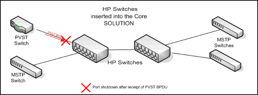
If an HP switch in the core of a network receives Per Vlan Spanning Tree (PVST) BPDUs and forwards the unrecognized PVST BPDUs on to MSTP-only switches, those switches then disconnect themselves from the network. This can create instability in the network infrastructure.
When the PVST protection feature is enabled on a port and a PVST BPDU is received on that port, the interface on which the PVST BPDU arrived is shut down, which isolates the sending switch from the rest of the network. An event message is logged and an SNMP notification trap is generated. The errant BPDU counter hpSwitchStpPortErrantBpduCounter is incremental. The PVST protection feature is enabled per-port.
|
|
|
|
|
NOTE: This is similar to the BPDU Guard feature where BPDU protection is applied to edge ports connected to end user devices that do not run STP. If STP BPDU packets are received on a protected port, the feature will disable that port and alert the network manager via an SNMP trap. |
|
|
If you configure a port for PVST filtering instead of PVST protection, the port remains in operation but traps are still generated and the BPDU counter hpSwitchStpPortErrantBpduCounter is incremented.
|
|
|
|
|
CAUTION: Enabling the PVST filter feature allows the port to continuously forward packets without spanning tree intervention, which could result in loop formation. If this occurs, disable the port and then reconfigure it with these commands:
|
|
|
In cases where spanning tree cannot be used to prevent loops at the edge of the network, loop protection may provide a suitable alternative. Loop protection operates in two modes:
|
The default mode. This mode can be used to find loops in untagged downlinks. |
|
|
Finds loops on tagged VLANs. This mode can be used to detect loops in tagged-only uplinks where STP cannot be enabled. |
The cases where loop protection might be chosen ahead of spanning tree to detect and prevent loops are as follows:
|
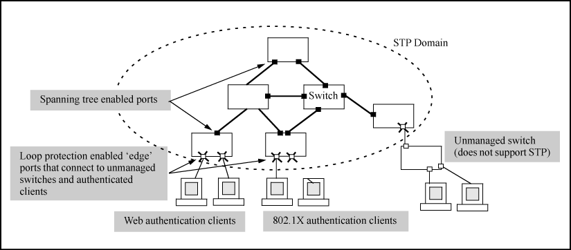
When spanning tree is enabled on a switch that use 802.1X, Web authentication and MAC authentication, loops may go undetected. For example, spanning tree packets that are looped back to an edge port will not be processed because they have a different broadcast/multicast MAC address from the client-authenticated MAC address. To ensure that client-authenticated edge ports get blocked when loops occur, you should enable loop protection on those ports. |
|
|
Spanning tree cannot detect the formation of loops where there is an unmanaged device on the network that does not process spanning tree packets and simply drops them. Loop protection has no such limitation and can be used to prevent loops on unmanaged switches. |
-
The
receiver-actionoption can be configured on a per-port basis and can only be enabled after loop protection has been enabled on the port. All other configuration options (disable-timer, trap loop-detected and transmit interval) are global. -
Regardless of how the
receiver-actionandtrapoptions are configured, all detected loops will be logged in the switch's event log. -
no loop-protect portcommand will not remove a receive-action configuration line from the running configuration unless this option is set to
receive-action send-disable. -
If
loop-protectis enabled in port mode, it cannot also be enabled in VLAN mode and vice-versa.