The permit or deny policy for IPv4 traffic you want to filter can be based on source address alone, or on source address plus other IPv4 factors.
-
Standard ACL: Uses only a packet's source IPv4 address as a criterion for permitting or denying the packet. For a standard ACL ID, use either a unique numeric string in the range of 1-99 or a unique name string of up to 64 alphanumeric characters.
-
Extended ACL: Offers the following criteria as options for permitting or denying a packet:
-
-
Any TCP traffic (only) for a specific TCP port or range of ports, including optional use of TCP control bits or control of connection (established) traffic based on whether the initial request should be allowed
-
Any UDP traffic (only) or UDP traffic for a specific UDP port
-
Any ICMP traffic (only) or ICMP traffic of a specific type and code
-
Any of the above with specific precedence and/or ToS settings (Applies to the HP Switch 2620 and 2920-series only)
For an extended ACL ID, use either a unique number in the range of 100-199 or a unique name string of up to 64 alphanumeric characters.
Carefully plan ACL applications before configuring specific ACLs.
After you enter an ACL command, you may want to inspect the resulting configuration. This is especially true where you are entering multiple ACEs into an ACL. Also, it is helpful to understand the configuration structure when using the following information.
The basic ACL structure includes four elements:
-
ACL identity and type: This identifies the ACL as
standardorextendedand shows the ACL name or number. -
One or more deny/permit list entries (ACEs): One entry per line.
Element Notes Type Standard or Extended Identifier -
Alphanumeric; Up to 64 Characters, Including Spaces
-
Numeric: 1-99 (Standard) or 100-199 (Extended)
Remark Allows up to 100 alphanumeric characters, including blank spaces. (If any spaces are used, the remark must be enclosed in a pair of single or double quotes.) A remark is associated with a particular ACE and will have the same sequence number as the ACE. (One remark is allowed per ACE.) Maximum ACEs per Switch The upper limit on ACEs supported by the switch depends on the concurrent resource usage by configured ACL, QoS, IDM, Mirroring, and other features. -
-
Implicit Deny:Where an ACL is in use, it denies any packets that do not have a match with the ACEs explicitly configured in the list. The Implicit Deny does not appear in ACL configuration listings, but always functions when the switch uses an ACL to filter packets. (You cannot delete the Implicit Deny, but you cansupersede it with a
permit anyorpermit ip any anystatement.)
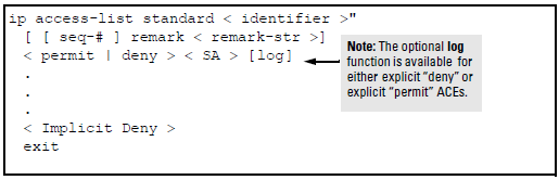
Individual ACEs in a standard ACL include only a permit/deny statement, the source addressing, and an optional log command (available with "deny" or "permit" statements).
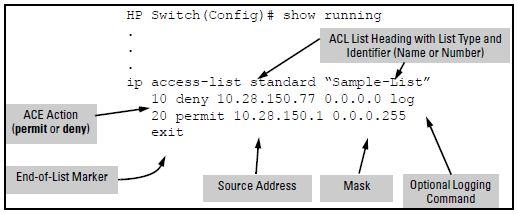
For example, A displayed standard ACL configuration with two ACEs shows how to interpret the entries in a standard ACL.
Individual ACEs in an extended ACL include:
-
A permit/deny statement
-
Source and destination IPv4 addressing
-
Choice of IPv4 criteria, including optional precedence and ToS
Optional ACL log command (for deny or permit entries)
General structure options for an extended ACL
ip access-list extended < identifier >
[ [ seq-3 ] remark < remark-str >]
< permit | deny > < ipv4-protocol-type > < SA > < src-acl-mask > < DA > dest-
acl-mask >

     < permit | deny > tcp
        < SA > [< operator > < value >]
        < DA > [< operator > < value >]

     < permit | deny > udp
        < SA > < src-acl-mask > [< operator > < port-id >]
        < DA > < dest-acl-mask > [< operator > < port-id >]

     < permit | deny > icmp
        < SA > < src-acl-mask > < DA > < dest-acl-mask > [icmp-type]

     < permit | deny > igmp
        < SA > < SA-mask > < DA > < dest-acl-mask > [igmp-type]

.  .  .
     < Implicit Deny >
     exit
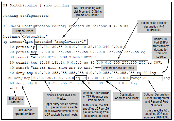
For example, Displayed extended ACL configuration shows how to interpret the entries in an extended ACL.
When the switch uses an ACL to determine whether to permit or deny a packet, it compares the packet to the criteria specified in the individual ACEs in the ACL, beginning with the first ACE in the list and proceeding sequentially until a match is found. When a match is found, the switch applies the indicated action (permit or deny) to the packet. This is significant because, once a match is found for a packet, subsequent ACEs in the same ACL will not be applied to that packet, regardless of whether they match the packet.
For example, suppose that you have applied the ACL shown in to inbound IPv4 traffic on VLAN 1 (the default VLAN):
Effect of the above ACL on inbound IPv4 traffic in the assigned VLAN
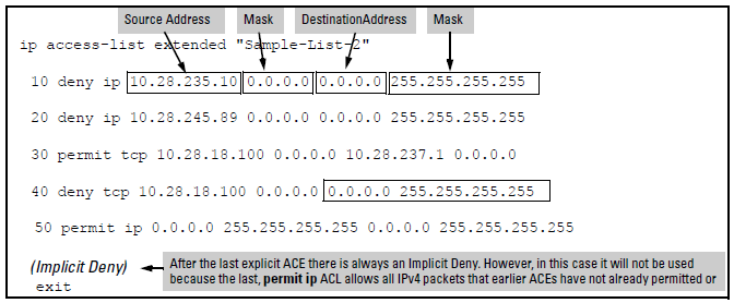
In any ACL having one or more ACEs there will always be a packet match. This is because the switch automatically applies an Implicit Deny as the last ACE in any ACL. This function is not visible in ACL listings, but is always present, see A standard ACL that permits all IPv4 traffic not implicitly denied. This means that if you configure the switch to use an ACL for filtering either inbound or outbound IPv4 traffic on a VLAN, any packets not specifically permitted or denied by the explicit entries you create will be denied by the Implicit Deny action. If you want to preempt the Implicit Deny (so that IPv4 traffic not specifically addressed by earlier ACEs in a given ACL will be permitted), insert an explicit permit any (for standard ACLs) or permit ip any any (for extended ACLs) as the last explicit ACE in the ACL.
The switch stores ACLs in the configuration file. Thus, until you actually assign an ACL to an interface, it is present in the configuration, but not used (and does not use any of the monitored resources, see "Monitored Resources" in the Management and Configuration Guide for your switch.)
In this case, if you subsequently create an ACL with that name or number, the switch automatically applies each ACE as soon as you enter it in the running-config file. Similarly, if you modify an existing ACE in an ACL you already applied to an interface, the switch automatically implements the new ACE as soon as you enter it. The switch allows up to 2048 ACLs each for IPv4 and determines the total from the number of unique ACL names in the configuration. For example, if you configure two ACLs, but assign only one of them to a VLAN, the ACL total is two, for the two unique ACL names. If you then assign the name of a nonexistent ACL to a VLAN, the new ACL total is three, because the switch now has three unique ACL names in its configuration. (RADIUS-based ACL resources are drawn from the IPv4 allocation).
(For a summary of ACL resource limits, see the appendix covering scalability in the latest Management and Configuration Guide for your switch.)
You can use either the switch CLI or an offline text editor to create an ACL. This section describes the CLI method, which is recommended for creating short ACLs.
These rules apply to all IPv4 ACEs you create or edit using the CLI:
-
Named IPv4 ACLs: Add an ACE to the end of a named ACE by using the
ip access-listcommand to enter the Named ACL (nacl) context and entering the ACE without the sequence number.For example, if you wanted to add a "permit" ACL at the end of a list named "List-1" to allow traffic from the device at 10.10.10.100:
HP Switch(config)# ip access-list standard List-1
HP Switch(config-std-nacl)# permit host 10.10.10.100
Insert an ACE anywhere in a named ACL by specifying a sequence number. For example, if you wanted to insert a new ACE as line 15 between lines 10 and 20 in an existing ACL named "List-2" to deny IPv4 traffic from the device at 10.10.10.77:
HP Switch(config)# ip access-list standard List-2
HP Switch(config-std-nacl)# 15 deny host 10.10.10.77
-
Numbered IPv4 ACLs: Add an ACE to the end of a numbered ACL by using the
access-list <1-99|100-199>command. For example, if you wanted to add a "permit" ACE at the end of a list identified with the number "11" to allow IPv4 traffic from the device at 10.10.10.100:HP Switch(config)# access-list 11 permit host 10.10.10.100
To insert an ACE anywhere in a numbered ACL, use the same process as described above for inserting an ACE anywhere in a named ACL. For example, to insert an ACE denying IPv4 traffic from the host at 10.10.10.77 as line 52 in an existing ACL identified (named) with the number 11:
HP Switch(config)# ip access-list standard 99
HP Switch(config-std-nacl)# 52 deny host 10.10.10.77
![[NOTE: ]](images/note.gif)
NOTE: After a numbered ACL has been created (using
access-list <1-99|100-199>), it can be managed as either a named or numbered ACL.
-
Deleting an ACE: Enter the ACL context and delete the sequence number for the unwanted ACE. (To view the sequence numbers of the ACEs in a list, use
show access-list <.)acl-name-str> config -
Duplicate ACEs are not allowed in the same ACL. Attempting to enter a duplicate ACE displays the
Duplicate access control entrymessage.
Use CIDR notation to enter ACL masks. The switch interprets the bits specified with CIDR notation as the address bits in an ACL and the corresponding address bits in a packet that must match. The switch then converts the mask to inverse notation for ACL use.
Examples of CIDR notation for masks
| Address used in an ACL with CIDR notation | Resulting ACL mask | Meaning |
|---|---|---|
| 10.38.240.125/15 | 0.1.255.255 | The leftmost 15 bits must match; the remaining bits are wildcards. |
| 10.38.240.125/20 | 0.0.15.255 | The leftmost 20 bits must match; the remaining bits are wildcards. |
| 10.38.240.125/21 | 0.0.7.255 | The leftmost 21 bits must match; the remaining bits are wildcards. |
| 10.38.240.125/24 | 0.0.0.255 | The leftmost 24 bits must match; the remaining bits are wildcards. |
| 18.38.240.125/32 | 0.0.0.0 | All bits must match. |