This section describes points to note regarding LLDP and CDP (Cisco Discovery Protocol) data received by the switch from other devices. LLDP operation includes both transmitting LLDP packets to neighbor devices and reading LLDP packets received from neighbor devices. CDP operation is limited to reading incoming CDP packets from neighbor devices. ( switches do not generate CDP packets.)
Incoming CDP and LLDP packets tagged for VLAN 1 are processed even if VLAN 1 does not contain any ports. VLAN 1 must be present, but it is typically present as the default VLAN for the switch.
|
|
|
![[NOTE: ]](images/note.gif) |
NOTE: The switch may pick up CDP and LLDP multicast packets from VLAN 1 even when CDP- and /or LLDP-enabled ports are not members of VLAN 1. |
|
|
With both LLDP and (read-only) CDP enabled on a switch port, the port can read both LLDP and CDP advertisements, and stores the data from both types of advertisements in its neighbor database. (The switch stores only CDP data that has a corresponding field in the LLDP neighbor database.) The neighbor database itself can be read by either LLDP or CDP methods or by using the show lldp commands. Take note of the following rules and conditions:
-
If the switch receives both LLDP and CDP advertisements on the same port from the same neighbor, the switch stores this information as two separate entries if the advertisements have different chassis ID and port ID information.
-
If the chassis and port ID information are the same, the switch stores this information as a single entry. That is, LLDP data overwrites the corresponding CDP data in the neighbor database if the chassis and port ID information in the LLDP and CDP advertisements received from the same device is the same.
-
Data read from a CDP packet does not support some LLDP fields, such as "System Descr," "SystemCapSupported," and "ChassisType." For such fields, LLDP assigns relevant default values. Also:
-
The LLDP "System Descr" field maps to CDP's "Version" and "Platform" fields.
-
The switch assigns "ChassisType" and "PortType" fields as "local" for both the LLDP and the CDP advertisements it receives.
-
Both LLDP and CDP support the "System Capability" TLV. However, LLDP differentiates between what a device is capable of supporting and what it is actually supporting, and separates the two types of information into subelements of the System Capability TLV. CDP has only a single field for this data. Thus, when CDP System Capability data is mapped to LLDP, the same value appears in both LLDP System Capability fields.
-
System Name and Port Descr are not communicated by CDP, and thus are not included in the switch's Neighbors database.
-
LLDP data transmission/collection and CDP data collection are both enabled in the switch's default configuration. In this state, an SNMP network management application designed to discover devices running either CDP or LLDP can retrieve neighbor information from the switch regardless of whether LLDP or CDP is used to collect the device-specific information.
|
Protocol state |
Packet generation |
Inbound data management |
Inbound packet forwarding |
|---|---|---|---|
|
CDP Enabled[1] |
N/A |
Store inbound CDP data. |
No forwarding of inbound CDP packets. |
|
CDP Disabled |
N/A |
No storage of CDP data from neighbor devices. |
Floods inbound CDP packets from connected devices to outbound ports. |
|
LLDP Enabled1 |
Generates and transmits LLDP packets out all ports on the switch. |
Store inbound LLDP data. |
No forwarding of inbound LLDP packets. |
|
LLDP Disabled |
No packet generation. |
No storage of LLDP data from neighbor devices. |
No forwarding of inbound LLDP packets. |
|
[1] Both CDP data collection and LLDP transmit/receive are enabled in the default configuration. If a switch receives CDP packets and LLDP packets from the same neighbor device on the same port, it stores and displays the two types of information separately if the chassis and port ID information in the two types of advertisements is different. In this case, if you want to use only one type of data from a neighbor sending both types, disable the unwanted protocol on either the neighbor device or on the switch. However, if the chassis and port ID information in the two types of advertisements is the same, the LLDP information overwrites the CDP data for the same neighbor device on the same port. |
|||
By default the switches have CDP enabled on each port. This is a read-only capability, meaning that the switch can receive and store information about adjacent CDP devices but does not generate CDP packets.
When a CDP-enabled switch receives a CDP packet from another CDP device, it enters that device's data in the CDP Neighbors table, along with the port number where the data was received—and does not forward the packet. The switch also periodically purges the table of any entries that have expired. (The hold time for any data entry in the switch's CDP Neighbors table is configured in the device transmitting the CDP packet and cannot be controlled in the switch receiving the packet.) A switch reviews the list of CDP neighbor entries every three seconds and purges any expired entries.
|
|
|
|
|
NOTE: For details on how to use an SNMP utility to retrieve information from the switch's CDP Neighbors table maintained in the switch's MIB, see the documentation provided with the particular SNMP utility. |
|
|
To standardize device discovery on all switches, LLDP will be implemented while offering limited read-only support for CDP, as documented in this manual. For the latest information on your switch model, consult the Release Notes (available on the Networking website.) If LLDP has not yet been implemented (or if you are running an older version of software), consult a previous version of the Management and Configuration Guide for device discovery details.
|
|
|
|
|
NOTE: LLDP-MED is an extension for LLDP, and the switch requires that LLDP be enabled as a prerequisite to LLDP-MED operation. |
|
|
An SNMP utility can progressively discover LLDP devices in a network by:
Also, by using show commands to access the switch's neighbor database for information collected by an individual switch, system administrators can learn about other devices connected to the switch, including device type (capability) and some configuration information. In VoIP deployments using LLDP-MED on the switches, additional support unique to VoIP applications is also available. See LLDP-MED.
An LLDP packet contains data about the transmitting switch and port. The switch advertises itself to adjacent (neighbor) devices by transmitting LLDP data packets out all ports on which outbound LLDP is enabled and by reading LLDP advertisements from neighbor devices on ports that are inbound LLDP-enabled. (LLDP is a one-way protocol and does not include any acknowledgement mechanism.) An LLDP-enabled port receiving LLDP packets inbound from neighbor devices stores the packet data in a Neighbor database (MIB.)
-
Where multiple LLDP devices are directly connected, an outbound LLDP packet travels only to the next LLDP device. An LLDP-capable device does not forward LLDP packets to any other devices, regardless of whether they are LLDP-enabled.
-
An intervening hub or repeater forwards the LLDP packets it receives in the same manner as any other multicast packets it receives. Thus, two LLDP switches joined by a hub or repeater handle LLDP traffic in the same way that they would if directly connected.
-
Any intervening 802.1D device or Layer-3 device that is either LLDP-unaware or has disabled LLDP operation drops the packet.
In the default configuration, LLDP is enabled and in both transmit and receive mode on all active ports. The LLDP configuration includes global settings, which apply to all active ports on the switch, and per-port settings, which affect only the operation of the specified ports.
The commands in the LLDP sections affect both LLDP and LLDP-MED operation.
In the default configuration, LLDP is globally enabled on the switch. To prevent transmission or receipt of LLDP traffic, you can disable LLDP operation.
In the default configuration for the switches, LLDP-MED is enabled by default which requires that LLDP is also enabled.
With LLDP enabled, the switch periodically transmits an LLDP advertisement (packet) out each active port enabled for outbound LLDP transmissions and receives LLDP advertisements on each active port enabled to receive LLDP traffic (Configuring per-port transmit and receive modes.) Per-port configuration options include four modes:
-
Transmit and receive (
tx_rx): This is the default setting on all ports. It enables a given port to both transmit and receive LLDP packets and to store the data from received (inbound) LLDP packets in the switch's MIB. -
Transmit only (
txonly): This setting enables a port to transmit LLDP packets that can be read by LLDP neighbors. However, the port drops inbound LLDP packets from LLDP neighbors without reading them. This prevents the switch from learning about LLDP neighbors on that port. -
Receive only (
rxonly): This setting enables a port to receive and read LLDP packets from LLDP neighbors and to store the packet data in the switch's MIB. However, the port does not transmit outbound LLDP packets. This prevents LLDP neighbors from learning about the switch through that port. -
Disable (
disable): This setting disables LLDP packet transmissions and reception on a port. In this state, the switch does not use the port for either learning about LLDP neighbors or informing LLDP neighbors of its presence.
You can enable the switch to send a notification to any configured SNMP trap receiver(s) when the switch detects a remote LLDP data change on an LLDP-enabled port (SNMP notification support.)
The following table lists the information the switch can include in the per-port, outbound LLDP packets it generates. In the default configuration, all outbound LLDP packets include this information in the TLVs transmitted to neighbor devices. However, you can configure LLDP advertisements on a per-port basis to omit some of this information (Configuring a remote management address for outbound LLDP advertisements.)
Data available for basic LLDP advertisements
|
Data type |
Configuration options |
Default |
Description |
|---|---|---|---|
|
Time-to-Live |
[1]. |
120 Seconds |
The length of time an LLDP neighbor retains the advertised data before discarding it. |
|
N/A |
Always Enabled |
Indicates the type of identifier used for Chassis ID. |
|
|
Chassis ID[6] |
N/A |
Always Enabled |
Uses base MAC address of the switch. |
|
N/A |
Always Enabled |
Uses "Local," meaning assigned locally by LLDP. |
|
|
Port Id[6] |
N/A |
Always Enabled |
Uses port number of the physical port. This is an internal number reflecting the reserved slot/port position in the chassis. |
|
Remote Management Address |
|||
|
N/A |
Always Enabled |
Shows the network address type. |
|
|
Address[4] |
Default or Configured |
Uses a default address selection method unless an optional address is configured. |
|
|
System Name[6] |
Enable/Disable |
Enabled |
Uses the switch's assigned name. |
|
System Description[6] |
Enable/Disable |
Enabled |
Includes switch model name and running software version, and ROM version. |
|
Port Description[6] |
Enable/Disable |
Enabled |
Uses the physical port identifier. |
|
Enable/Disable |
Enabled |
Identifies the switch's primary capabilities (bridge, router.) |
|
|
Enable/Disable |
Enabled |
Identifies the primary switch functions that are enabled, such as routing. |
|
|
[1] The packet time-to-live value is included in LLDP data packets. (See Changing the time-to-live for transmitted advertisements.) [2] Subelement of the Chassis ID TLV. [6] Populated with data captured internally by the switch. For more on these data types, refer to the IEEE P802.1AB Standard. [3] Subelement of the Port ID TLV. [4] Subelement of the Remote-Management-Address TLV. [5] Subelement of the System Capability TLV. |
|||
You can extract LLDP information from the switch to identify adjacent LLDP devices. Options include:
-
Using the switch's
show lldp infocommand options to display data collected on adjacent LLDP devices—as well as the local data the switch is transmitting to adjacent LLDP devices (Viewing the global LLDP, port admin, and SNMP notification status.) -
Using an SNMP application that is designed to query the Neighbors MIB for LLDP data to use in device discovery and topology mapping.
-
Using the
walkmibcommand to display a listing of the LLDP MIB objects
The operation covered by this section is compatible with these standards:
-
ANSI/TIA-1057/D6 (LLDP-MED; refer to LLDP-MED.)
LLDP manages trunked ports individually. That is, trunked ports are configured individually for LLDP operation, in the same manner as non-trunked ports. Also, LLDP sends separate advertisements on each port in a trunk, and not on a per-trunk basis. Similarly, LLDP data received through trunked ports is stored individually, per-port.
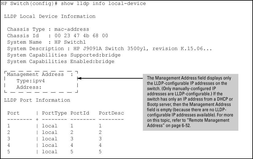
In the default operation, if a port belongs to only one static VLAN, the port advertises the lowest-order IP address configured on that VLAN. If a port belongs to multiple VLANs, the port advertises the lowest-order IP address configured on the VLAN with the lowest VID. If the qualifying VLAN does not have an IP address, the port advertises 127.0.0.1 as its IP address. For example, if the port is a member of the default VLAN (VID=1), and there is an IP address configured for the default VLAN, the port advertises this IP address. In the default operation, the IP address that LLDP uses can be an address acquired by DHCP or Bootp.
You can override the default operation by configuring the port to advertise any IP address that is manually configured on the switch, even if the port does not belong to the VLAN configured with the selected IP address (Configuring a remote management address for outbound LLDP advertisements.) (Note that LLDP cannot be configured through the CLI to advertise an addresses acquired through DHCP or Bootp. However, as mentioned above, in the default LLDP configuration, if the lowest-order IP address on the VLAN with the lowest VID for a given port is a DHCP or Bootp address, the switch includes this address in its LLDP advertisements unless another address is configured for advertisements on that port.) Also, although LLDP allows configuring multiple remote management addresses on a port, only the lowest-order address configured on the port will be included in outbound advertisements. Attempting to use the CLI to configure LLDP with an IP address that is either not configured on a VLAN or has been acquired by DHCP or Bootp results in the following error message.
xxx.xxx.xxx.xxx: This IP address is not configured or is a DHCP address.
The Time-to-Live value (in seconds) for all LLDP advertisements transmitted from a switch is controlled by the switch that generates the advertisement and determines how long an LLDP neighbor retains the advertised data before discarding it. The Time-to-Live value is the result of multiplying the refresh-interval by the holdtime-multiplier.
The switch uses a delay-interval setting to delay transmitting successive advertisements resulting from these LLDP MIB changes. If a switch is subject to frequent changes to its LLDP MIB, lengthening this interval can reduce the frequency of successive advertisements. You can change the delay-interval by using either an SNMP network management application or the CLI setmib command.
In the default configuration, a port receiving a disable command followed immediately by a txonly, rxonly, or tx_rx command delays re-initializing for two seconds, during which LLDP operation remains disabled. If an active port is subjected to frequent toggling between the LLDP disabled and enabled states, LLDP advertisements are more frequently transmitted to the neighbor device. Also, the neighbor table in the adjacent device changes more frequently as it deletes, then replaces LLDP data for the affected port which, in turn, generates SNMP traps (if trap receivers and SNMP notification are configured.) All of this can unnecessarily increase network traffic. Extending the re-initialization-delay interval delays the ability of the port to re-initialize and generate LLDP traffic following an LLDP disable/enable cycle.
You can enable SNMP trap notification of LLDP data changes detected on advertisements received from neighbor devices and control the interval between successive notifications of data changes on the same neighbor.
If LLDP trap notification is enabled on a port, a rapid succession of changes in LLDP information received in advertisements from one or more neighbors can generate a high number of traps. To reduce this effect, you can globally change the interval between successive notifications of neighbor data change.
In the default LLDP configuration, outbound advertisements from each port on the switch include both mandatory and optional data.
An active LLDP port on the switch always includes the mandatory data in its outbound advertisements. LLDP collects the mandatory data, and, except for the Remote Management Address, you cannot use LLDP commands to configure the actual data.
You can configure an individual port or group of ports to exclude one or more of the following data types from outbound LLDP advertisements.
Optional data types, when enabled, are populated with data internal to the switch; that is, you cannot use LLDP commands to configure their actual content.
This feature is optional for LLDP operation, but is required for LLDP-MED operation.
Port speed and duplex advertisements are supported on the switches to inform an LLDP endpoint and the switch port of each other's port speed and duplex configuration and capabilities. Configuration mismatches between a switch port and an LLDP endpoint can result in excessive collisions and voice quality degradation. LLDP enables discovery of such mismatches by supporting SNMP access to the switch MIB for comparing the current switch port and endpoint settings. (Changing a current device configuration to eliminate a mismatch requires intervention by the system operator.)
An SNMP network management application can be used to compare the port speed and duplex data configured in the switch and advertised by the LLDP endpoint. You can also use the CLI to display this information.
The port-vlan-id option enables advertisement of the port VLAN ID TLV as part of the regularly advertised TLVs. This allows discovery of a mismatch in the configured native VLAN ID between LLDP peers. The information is visible using show commands and is logged to the Syslog server.
The LLDP-EXT-DOT1-MIB has the corresponding MIB variables for the Port VLAN ID TLV. The TLV advertisement can be enabled or disabled using the MIB object lldpXdot1ConfigPortVlanTxEnable in the lldpXdot1ConfigPortVlanTable.
The port VLAN ID TLV local information can be obtained from the MIB object lldpXdot1LocPortVlanId in the local information table lldpXdot1LocTable.
The port VLAN ID TLV information about all the connected peer devices can be obtained from the MIB object lldpXdot1RemPortVlanId in the remote information table lldpXdot1RemTable.
LLDP-MED (ANSI/TIA-1057/D6) extends the LLDP (IEEE 802.1AB) industry standard to support advanced features on the network edge for Voice Over IP (VoIP) endpoint devices with specialized capabilities and LLDP-MED standards-based functionality. LLDP-MED in the switches uses the standard LLDP commands described earlier in this section, with some extensions, and also introduces new commands unique to LLDP-MED operation. The show commands described elsewhere in this section are applicable to both LLDP and LLDP-MED operation. LLDP-MED benefits include:
-
Plug-and-play provisioning for MED-capable, VoIP endpoint devices
-
Simplified, vendor-independent management enabling different IP telephony systems to interoperate on one network
-
Automatic deployment of convergence network policies (voice VLANs, Layer 2/CoS priority, and Layer 3/QoS priority)
-
Configurable endpoint location data to support the Emergency Call Service (ECS) (such as Enhanced 911 service, 999, 112)
-
Detailed VoIP endpoint data inventory readable via SNMP from the switch
-
Power over Ethernet (PoE) status and troubleshooting support via SNMP
-
support for IP telephony network troubleshooting of call quality issues via SNMP
This section describes how to configure and use LLDP-MED features in the switches to support VoIP network edge devices (media endpoint devices) such as:
LLDP-MED interoperates with directly connected IP telephony (endpoint) clients having these features and services:
-
Auto-negotiate speed and duplex configuration with the switch
-
Use the following network policy elements configured on the client port
-
Discover and advertise device location data learned from the switch
-
Advertise device information for the device data inventory collected by the switch, including:
-
Provide information on network connectivity capabilities (for example, a multi-port VoIP phone with Layer 2 switch capability)
|
|
|
|
|
NOTE: LLDP-MED is intended for use with VoIP endpoints and is not designed to support links between network infrastructure devices, such as switch-to-switch or switch-to-router links. |
|
|
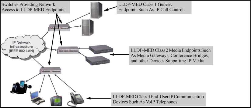
LLDP-MED endpoint devices are, by definition, located at the network edge and communicate using the LLDP-MED framework. Any LLDP-MED endpoint device belongs to one of the following three classes:
-
Class 1 (generic endpoint devices): These devices offer the basic LLDP discovery services, network policy advertisement (VLAN ID, Layer 2/802.1p priority, and Layer 3/DSCP priority), and PoE management. This class includes such devices as IP call controllers and communication-related servers.
-
Class 2 (media endpoint devices): These devices offer all Class 1 features plus media-streaming capability, and include such devices as voice/media gateways, conference bridges, and media servers.
-
Class 3 (communication devices): These devices are typically IP phones or end-user devices that otherwise support IP media and offer all Class 1 and Class 2 features, plus location identification and emergency 911 capability, Layer 2 switch support, and device information management.
The switches offer two configurable TLVs supporting MED-specific capabilities:
Syntax
lldp admin-status <PORT-LIST>txonly | rxonly | tx_rx | disable
With LLDP enabled on the switch in the default configuration, each port is configured to transmit and receive LLDP packets. These options enable you to control which ports participate in LLDP traffic and whether the participating ports allow LLDP traffic in only one direction or in both directions.
|
|
Configures the specified ports to transmit LLDP packets, but block inbound LLDP packets from neighbor devices. |
|
|
Configures the specified ports to receive LLDP packets from neighbors, but block outbound packets to neighbors. |
|
|
Configures the specified ports to both transmit and receive LLDP packets. (This is the default setting.) |
|
|
Disables LLDP packet transmit and receive on the specified ports. |
This is an optional command you can use to include a specific IP address in the outbound LLDP advertisements for specific ports.
Syntax
[no] lldp config <PORT-LIST> ipAddrEnable ip-address
Replaces the default IP address for the port with an IP address you specify. This can be any IP address configured in a static VLAN on the switch, even if the port does not belong to the VLAN configured with the selected IP address.
The no form of the command deletes the specified IP address.
If there are no IP addresses configured as management addresses, the IP address selection method returns to the default operation.
Default: The port advertises the IP address of the lowest-numbered VLAN (VID) to which it belongs. If there is no IP address configured on the VLANs to which the port belongs, and if the port is not configured to advertise an IP address from any other (static) VLAN on the switch, the port advertises an address of 127.0.0.1.)
|
|
|
|
|
NOTE: This command does not accept either IP addresses acquired through DHCP or Bootp, or IP addresses that are not configured in a static VLAN on the switch. |
|
|
Example
If port 3 belongs to a subnetted VLAN that includes an IP address of 10.10.10.100 and you want port 3 to use this secondary address in LLDP advertisements, you need to execute the following command:
(HP_Switch_name#) lldp config 3 ipAddrEnable 10.10.10.100
Syntax
[no] lldp config <PORT-LIST> basicTlvEnable TLV-Type
|
|
For outbound LLDP advertisements, this TLV includes an alphanumeric string describing the port. (Default: Enabled) |
|
|
For outbound LLDP advertisements, this TLV includes an alphanumeric string showing the assigned name of the system. (Default: Enabled) |
|
|
For outbound LLDP advertisements, this TLV includes an alphanumeric string describing the full name and version identification for the hardware type, software version, and networking application of the system. (Default: Enabled) |
|
|
For outbound advertisements, this TLV includes a bitmask of supported system capabilities (device functions.) Also includes information on whether the capabilities are enabled. (Default: Enabled) |
Example
If you want to exclude the system name TLV from the outbound LLDP advertisements for all ports on a switch, use this command:
(HP_Switch_name#) no lldp config 1-24 basicTlvEnable system_name
If you later decide to reinstate the system name TLV on ports 1-5, use this command:
(HP_Switch_name#) lldp config 1-5 basicTlvEnable system_name
Syntax
[no] lldp config <PORT-LIST> dot3TlvEnable macphy_config
For outbound advertisements, this TLV includes the (local) switch port's current speed and duplex settings, the range of speed and duplex settings the port supports, and the method required for reconfiguring the speed and duplex settings on the device (autonegotiation during link initialization, or manual configuration.)
Using SNMP to compare local and remote information can help in locating configuration mismatches.
|
|
|
|
|
NOTE: For LLDP operation, this TLV is optional. For LLDP-MED operation, this TLV is mandatory. |
|
|
Syntax
[no] lldp config <PORT-LIST> medPortLocation Address-Type
Configures location of emergency call data the switch advertises per port in the location_id TLV. This TLV is for use by LLDP-MED endpoints employing location-based applications.
|
|
|
|
|
NOTE: The switch allows one medPortLocation entry per port (without regard to type.) Configuring a new medPortLocation entry of any type on a port replaces any previously configured entry on that port. |
|
|
civic-addr [ COUNTRY-STR WHAT CA-TYPE CA-VALUE …CA-TYPE CA-VALUE ]… [ CA-TYPE CA-VALUE ]
Enables configuration of a physical address on a switch port and allows up to 75 characters of address information.
|
|
A two-character country code, as defined by ISO 3166. Some examples include |
||||||
|
|
A single-digit number specifying the type of device to which the location data applies:
This field is required in a |
||||||
|
|
A series of data pairs, each composed of a location data "type" specifier and the corresponding location data for that type. That is, the first value in a pair is expected to be the civic address "type" number ( For example, if the Multiple type/value pairs can be entered in any order, although Hewlett Packard Enterprise recommends that multiple pairs be entered in ascending order of the When an emergency call is placed from a properly configured class 3 endpoint device to an appropriate PSAP, the country code, device type, and type/value pairs configured on the switch port are included in the transmission. The "type" specifiers are used by the PSAP to identify and organize the location data components in an understandable format for response personnel to interpret. A
(Range: 0 - 255)
Strings are delimited by either blank spaces, single quotes (' … '), or double quotes ("… ".) Each string should represent a specific data type in a set of unique type/value pairs comprising the description of a location, and each string must be preceded by a
|
||||||
|
|
This feature is intended for use in ECS applications to support class 3 LLDP-MED VoIP telephones connected to a switch in an MLTS infrastructure. An ELIN is a valid NANP format telephone number assigned to MLTS operators in North America by the appropriate authority. The ELIN is used to route emergency (E911) calls to a PSAP. (Range: 1-15 numeric characters) |
Syntax
[no] lldp enable-notification <PORT-LIST>
Enables or disables each port in <PORT-LIST> for sending notification to configured SNMP trap receivers if an LLDP data change is detected in an advertisement received on the port from an LLDP neighbor.
Example
This command enables SNMP notification on ports 1 - 5:
(HP_Switch_name#) lldp enable-notification 1-5
Syntax
[no] lldp run
Enables or disables LLDP operation on the switch.
The no form of the command, regardless of individual LLDP port configurations, prevents the switch from transmitting outbound LLDP advertisements and causes the switch to drop all LLDP advertisements received from other devices.
The switch preserves the current LLDP configuration when LLDP is disabled. After LLDP is disabled, the information in the LLDP neighbors database remains until it times-out.
Example
To disable LLDP on the switch:
(HP_Switch_name#) no lldp run
Syntax
lldp fast-start-count 1 - 10
An LLDP-MED device connecting to a switch port may use the data contained in the MED TLVs from the switch to configure itself. However, the lldp refresh-interval setting (default: 30 seconds) for transmitting advertisements can cause an unacceptable delay in MED device configuration.
To support rapid LLDP-MED device configuration, the lldp fast-start-count command temporarily overrides the refresh-interval setting for the fast-start-count advertisement interval. This results in the port initially advertising LLDP-MED at a faster rate for a limited time. Thus, when the switch detects a new LLDP-MED device on a port, it transmits one LLDP-MED advertisement per second out the port for the duration of the fast-start-count interval. In most cases, the default setting should provide an adequate fast-start-count interval.
|
|
|
|
|
NOTE: This global command applies only to ports on which a new LLDP-MED device is detected. It does not override the |
|
|
This interval controls how often active ports retransmit advertisements to their neighbors.
Syntax
lldp refresh-interval <5 - 32768>
Changes the interval between consecutive transmissions of LLDP advertisements on any given port.
|
|
|
|
|
NOTE: The |
|
|
Syntax
lldp holdtime-multiplier 2 - 10
Changes the multiplier an LLDP switch uses to calculate the Time-to-Live for the LLDP advertisements it generates and transmits to LLDP neighbors. When the Time-to-Live for a given advertisement expires, the advertised data is deleted from the neighbor switch's MIB.
Example
If the refresh-interval on the switch is 15 seconds and the holdtime-multiplier is at the default, the Time-to-Live for advertisements transmitted from the switch is 60 seconds (4 x 15.)
To reduce the Time-to-Live, you could lower the holdtime-interval to 2, which would result in a Time-to-Live of 30 seconds.
(HP_Switch_name#) lldp holdtime-multiplier 2
To change the delay interval between advertisements generated by value or status changes to the LLDP MIB, use the following command.
Syntax
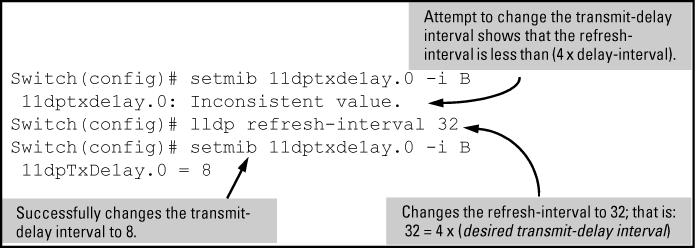
setmib lldpTxDelay.0 -i 1 - 8192
Uses setmib to change the minimum time (delay-interval) any LLDP port will delay advertising successive LLDP advertisements because of a change in LLDP MIB content.
|
|
|
|
|
NOTE: For the 5400zl, and 3800 switches, when the switch is in enhanced secure mode, the following prompt appears before the sensitive information for the setmib command is displayed: The setmib command should not be used in enhanced secure mode.For more information, see the access security guide. |
|
|
Example
To change the delay-interval from 2 seconds to 8 seconds when the refresh-interval is at the default 30 seconds, you must first set the refresh-interval to a minimum of 32 seconds (32 = 4 x 8.) (See Changing the transmit-delay interval.)
Syntax
setmib lldpReinitDelay.0 -i <1-10>
Uses setmib to change the minimum time (reinitialization delay interval) an LLDP port will wait before reinitializing after receiving an LLDP disable command followed closely by a txonly or tx_rx command. The delay interval commences with execution of the lldp admin-status command.<PORT-LIST> disable
(Default: 2 seconds; Range 1–10 seconds)
Example
The following command changes the reinitialization delay interval to five seconds:
(HP_Switch_name#) setmib lldpreinitdelay.0 -i 5
This enhancement filters out PVID mismatch log messages on a per-port basis. PVID mismatches are logged when there is a difference in the PVID advertised by a neighboring switch and the PVID of the switch port which receives the LLDP advertisement. Logging is an LLDP feature that allows detection of possible vlan leakage between adjacent switches. However, if these events are logged too frequently, they can overwhelm the log buffer and push relevant logging data out of log memory, making it difficult to troubleshoot another issue.
Logging is disabled and enabled with the support of CLI commands.
This enhancement also includes displaying the Mac-Address in the PVID mismatch log message when the port ID is Mac-Address instead of displaying garbage characters in the peer device port ID field.
Use the following command to disable the logging of the PVID mismatch log messages:
Syntax
Syntax
Syntax
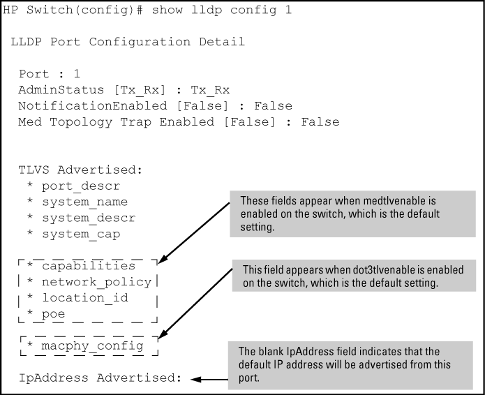
show lldp config <PORT-LIST>
Displays the LLDP port-specific configuration for all ports in <PORT-LIST> , including which optional TLVs and any non-default IP address that are included in the port's outbound advertisements.
Syntax
show lldp info local-device<PORT-LIST>
Without the <PORT-LIST>
With the <PORT-LIST>
|
|
|
|
|
NOTE: This command displays the information available on the switch. Use the |
|
|
Example
In the default configuration, the switch information currently available for outbound LLDP advertisements appears similar to the display in Displaying the global and per-port information available for outbound advertisements.
Syntax
show lldp stats<PORT-LIST>
The global LLDP statistics command displays an overview of neighbor detection activity on the switch, plus data on the number of frames sent, received, and discarded per-port.
The per-port LLDP statistics command enhances the list of per-port statistics provided by the global statistics command with some additional per-port LLDP statistics.
|
|
The elapsed time since a neighbor was last added or deleted. |
|
|
The total of new LLDP neighbors detected since the last switch reboot. Disconnecting, and then reconnecting a neighbor increments this counter. |
|
|
The number of neighbor deletions from the MIB for AgeOut Count and forced drops for all ports. For example, if the admin status for port on a neighbor device changes from The device receiving the shutdown packet deletes all information about the neighbor received on the applicable inbound port and increments the counter. |
|
|
The number of valid LLDP neighbors the switch detected, but could not add. This can occur, for example, when a new neighbor is detected when the switch is already supporting the maximum number of neighbors. See Neighbor maximum. |
|
|
The number of LLDP neighbors dropped on all ports because of Time-to-Live expiring. |
|
|
The total number of valid, inbound LLDP advertisements received from any neighbors on Where multiple neighbors are connected to a port through a hub, this value is the total number of LLDP advertisements received from all sources. |
|
|
The total number of LLDP advertisements sent from |
|
|
The total number of inbound LLDP advertisements discarded by This can occur, for example, when a new neighbor is detected on the port, but the switch is already supporting the maximum number of neighbors. See Neighbor maximum. This can also be an indication of advertisement formatting problems in the neighbor device. |
|
|
The total number of invalid LLDP advertisements received on the port. An invalid advertisement can be caused by header formatting problems in the neighbor device. |
|
|
The total number of LLDP TLVs received on a port with a type value in the reserved range. This can be caused by a basic management TLV from a later LLDP version than the one currently running on the switch. |
|
|
The total number of LLDP TLVs discarded for any reason. In this case, the advertisement carrying the TLV may be accepted, but the individual TLV is not usable. |
|
|
The number of LLDP neighbors dropped on the port because of Time-to-Live expiring. |
Examples
A global LLDP statistics display
(HP_Switch_name#) show lldp stats

 LLDP Device Statistics

  Neighbor Entries List Last Updated : 2 hours
  New Neighbor Entries Count : 20
  Neighbor Entries Deleted Count : 20
  Neighbor Entries Dropped Count : 0
  Neighbor Entries AgeOut Count : 20

 LLDP Port Statistics

  Port   | NumFramesRecvd NumFramesSent NumFramesDiscarded
  ------ + -------------- ------------- ------------------
  A1     | 97317          97843         0
  A2     | 21             12            0
  A3     | 0              0             0
  A4     | 446            252           0
  A5     | 0              0             0
  A6     | 0              0             0
  A7     | 0              0             0
  A8     | 0              0             0
In the default configuration, LLDP is enabled and in both transmit and receive mode on all active ports. The LLDP configuration includes global settings that apply to all active ports on the switch, and per-port settings that affect only the operation of the specified ports.
The commands in this section affect both LLDP and LLDP-MED operation.
Syntax
show lldp config
Displays the LLDP global configuration, LLDP port status, and SNMP notification status.
Example of viewing the general LLDP configuration
show lldp config produces the following display when the switch is in the default LLDP configuration:
(HP_Switch_name#) show lldp config

LLDP Global Configuration

LLDP Enabled [Yes] :             Yes
LLDP Transmit Interval [30] :    30
LLDP Hold time Multiplier [4] :  4
LLDP Delay Interval [2] :        2
LLDP Reinit Interval [2] :       2
LLDP Notification Interval [5] : 5
LLDP Fast Start Count [5] :      5

LLDP Port Configuration
Port | AdminStatus NotificationEnabled  Med Topology Trap Enabled
---- + ----------- -------------------  -------------------------
A1 |    Tx_Rx          False            False
A2 |    Tx_Rx          False            False
A3 |    Tx_Rx          False            False
A4 |    Tx_Rx          False            False
A5 |    Tx_Rx          False            False
A6 |    Tx_Rx          False            False
A7 |    Tx_Rx          False            False
A8 |    Tx_Rx          False            False
|
|
|
|
|
NOTE: The values displayed in the LLDP column correspond to the |
|
|
This optional feature provides information an SNMP application can use to track LLDP-MED connects and disconnects.
Syntax
lldp top-change-notify <PORT-LIST>
Topology change notification, when enabled on an LLDP port, causes the switch to send an SNMP trap if it detects LLDP-MED endpoint connection or disconnection activity on the port, or an age-out of the LLDP-MED neighbor on the port. The trap includes the following information:
-
The port number (internal) on which the activity was detected.
-
The LLDP-MED class of the device detected on the port.
The show running command shows whether the topology change notification feature is enabled or disabled. For example, if ports A1 to A10 have topology change notification enabled, the following entry appears in the show running output:
lldp top-change-notify A1-A10
The medTlvEnable option on the switch is enabled in the default configuration and supports the following LLDP-MED TLVs:
|
|
|
|
|
NOTE: LLDP-MED operation requires the macphy_config TLV subelement (enabled by default) that is optional for IEEE 802.1AB LLDP operation. For more information, see the |
|
|
Network policy advertisements are intended for real-time voice and video applications, and include these TLV subelements:
These rules affect advertisements of VLANs in network policy TLVs:
-
The VLAN ID TLV subelement applies only to a VLAN configured for voice operation (
vlan.)vidvoice -
If there are multiple voice VLANs configured on a port, LLDP-MED advertises the voice VLAN having the lowest VID.
-
The voice VLAN port membership configured on the switch can be tagged or untagged. However, if the LLDP-MED endpoint expects a tagged membership when the switch port is configured for untagged, or the reverse, a configuration mismatch results. (Typically, the endpoint expects the switch port to have a tagged voice VLAN membership.)
-
If a given port does not belong to a voice VLAN, the switch does not advertise the VLAN ID TLV through this port.
These policy elements may be statically configured on the switch or dynamically imposed during an authenticated session on the switch using a RADIUS server and 802.1X or MAC authentication. (Web authentication does not apply to VoIP telephones and other telecommunications devices that are not capable of accessing the switch through a Web browser.) The QoS and voice VLAN policy elements can be statically configured with the following CLI commands:
These advertisements inform an LLDP-MED endpoint of the power (PoE) configuration on switch ports. Similar advertisements from an LLDP-MED endpoint inform the switch of the endpoint's power needs and provide information that can be used to identify power priority mismatches.
PoE TLVs include the following power data:
You can configure a switch port to advertise location data for the switch itself, the physical wall-jack location of the endpoint (recommended), or the location of a DHCP server supporting the switch, endpoint, or both. You also have the option of configuring these different address types:
Latitude, longitude, and altitude data can be configured per switch port using an SNMP management application. For more information, see the documentation provided with the application. A further source of information on this topic is the RFC 3825: Dynamic Host Configuration Protocol Option for Coordinate-based Location Configuration Information.
|
|
|
|
|
NOTE: Endpoint use of data from a medPortLocation TLV sent by the switch is device-dependent. See the documentation provided with the endpoint device. |
|
|
The code assignments in the following table are examples from a work-in-progress (the internet draft titled "Dynamic Host Configuration Protocol (DHCPv4 and DHCPv6) Option for Civic Addresses Configuration Information draft-ietf-geopriv-dhcp-civil-06" dated May 30, 2005.) For the actual codes to use, contact the PSAP or other authority responsible for specifying the civic addressing data standard for your network.
Some location codes used in CA-TYPE fields
|
Location element |
Code |
Location element |
Code |
|---|---|---|---|
|
national subdivision |
1 |
street number |
19 |
|
regional subdivision |
2 |
additional location data |
22 |
|
city or township |
3 |
unit or apartment |
26 |
|
city subdivision |
4 |
floor |
27 |
|
street |
6 |
room number |
28 |
|
street suffix |
18 |
Example
Suppose a system operator wants to configure the following information as the civic address for a telephone connected to her company's network through port A2 of a switch at the following location:
|
Description |
CA-type |
CA-VALUE |
|---|---|---|
|
national subdivision |
1 |
CA |
|
city |
3 |
Widgitville |
|
street |
6 |
Main |
|
street number |
19 |
1433 |
|
unit |
26 |
Suite 4-N |
|
floor |
27 |
4 |
|
room number |
28 |
N4-3 |
Example of a civic address configuration shows the commands for configuring and displaying the above data.
Example of a civic address configuration
(HP_Switch_name#) lldp config 2 medportlocation civic-addr US 2 1 CA 3
Widgitville 6 Main 19 1433 26 Suite_4—N 27 4 28 N4—3

(HP_Switch_name#) show lldp config 2
 LLDP Port Configuration Detail
  Port : A2
  AdminStatus [Tx_Rx] : Tx_Rx
  NotificationEnabled [False] : False
  Med Topology Trap Enabled [False] : False
  Country Name          : US
  What                  : 2
  Ca-Type               : 1
  Ca-Length             : 2
  Ca-Value              : CA
  Ca-Type               : 3
  Ca-Length             : 11
  Ca-Value              : Widgitville
  Ca-Type               : 6
  Ca-Length             : 4
  Ca-Value              : Main
  Ca-Type               : 19
  Ca-Length             : 4
  Ca-Value              : 1433
  Ca-Type               : 26
  Ca-Length             : 9
  Ca-Value              : Suite_4-N
  Ca-Type               : 27
  Ca-Length             : 1
  Ca-Value              : 4
  Ca-Type               : 28
  Ca-Length             : 4
  Ca-Value              : N4-3
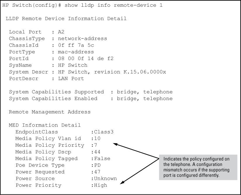
You can compare port speed and duplex information for a switch port and a connected LLDP-MED endpoint for configuration mismatches by using an SNMP application. You can also use the switch CLI to display this information, if necessary. The show interfaces brief and <PORT-LIST>show lldp info remote-device commands provide methods for displaying speed and duplex information for switch ports. For information on displaying the currently configured port speed and duplex on an LLDP-MED endpoint.<PORT-LIST>
LLDP statistics are available on both a global and a per-port levels. Rebooting the switch resets the LLDP statistics counters to zero. Disabling the transmit and/or receive capability on a port "freezes" the related port counters at their current values.
Beginning with switch software release 16.01, LLDP over OOBM is supported on the following switch models covered in this guide:
-
3800 (KA software)
-
3810 (KB software)
-
5400R (KB software)
The following commands enable the user to configure LLDP for OOBM ports.
This command sets the OOBM port operational mode.
Syntax Parameters/OptionsThis command enables or disables notification on the OOBM port.
Syntax SpecifiersEnables notification on the OOBM port.
Parameters/Options Example output/response/...switch(config)#lldp enable-notification ? oobm Enable or disable notification on the OOBM port. [ethernet] PORT-LIST Enable notification on the specified ports.
This command shows LLDP configuration information.
Syntax Parameters/OptionsShows port-list configuration information.
Shows oobm LLDP configuration information.
Example
switch(config)#show lldp config

LLDP Global Configuration

  LLDP Enabled [Yes] : Yes
  LLDP Transmit Interval    [30] : 30
  LLDP Hold time Multiplier  [4] : 4
  LLDP Delay Interval        [2] : 2
  LLDP Reinit Interval       [2] : 2
  LLDP Notification Interval [5] : 5
  LLDP Fast Start Count      [5] : 5


 LLDP Port Configuration

  Port   | AdminStatus NotificationEnabled Med Topology Trap Enabled
  ------ + ----------- ------------------- -------------------------
  1      | Tx_Rx       False               False
  2      | Tx_Rx       False               False
  3      | Tx_Rx       False               False
  4      | Tx_Rx       False               False
  5      | Tx_Rx       False               False
  6      | Tx_Rx       False               False
  7      | Tx_Rx       False               False
  8      | Tx_Rx       False               False
  9      | Tx_Rx       False               False


OOBM    | Tx_Rx       False               False
This command shows oobm LLDP configuration information.
Syntax Exampleswitch(config)#show lldp config oobm LLDP Port Configuration Detail Port : OOBM AdminStatus [Tx_Rx] : Tx_Rx NotificationEnabled [False] : False Med Topology Trap Enabled [False] : False TLVS Advertised: * port_descr * system_name * system_descr * system_cap IpAddress Advertised: * 10.0.0.1
This command shows LLDP information about a local or remote device.
Syntax Parameters/OptionsShows LLDP information about a local device.
Shows LLDP information about a remote device.
Sub-parametersThe following are next level parameters of a local-or remote-device.
Shows port-list configuration information.
Shows oobm LLDP configuration information.
This command shows LLDP information about a local device.
Syntax Example
switch(config)# show lldp info local-device

LLDP Local Device Information

  Chassis Type : mac-address
  Chassis Id   : 08 2e 5f 69 8c 00
  System Name  : HPE Switch
  System Description : HPE Switch, revision XX.15.15.000...
  System Capabilities Supported: bridge, router
  System Capabilities Enabled: bridge

  Management Address  :
     Type: ipv4
     Address: 20.0.0.1


OOBM Management Address:
     Type: ipv4
     Address: 100.0.0.1


 LLDP Port Information

  Port     PortType PortId   PortDesc
  -------- -------- -------- --------
  1        local    1        1
  2        local    2        2
  3        local    3        3
  4        local    4        4
  5        local    5        5


OOBM      local    4000     OOBM
This command shows LLDP information about a remote device for the specified oobm ports.
Syntax Example
switch(config)# show lldp info remote-device oobm

 LLDP Remote Device Information Detail

  Local Port   : OOBM
  ChassisType  : mac-address
  ChassisId    : b4 b5 2f a8 84 00
  PortType     : local
  PortId       : 21
  SysName      : HPE Switch
  System Descr : HPE Switch, revision XX.15.15.000...
  PortDescr    : 21
  Pvid         :

  System Capabilities Supported  : bridge, router
  System Capabilities Enabled    : bridge

  Remote Management Address
     Type    : all802
     Address : b4 b5 2f a8 84 00
Example
switch(config)# show lldp info remote-device 21

 LLDP Remote Device Information Detail

  Local Port   : 21
  ChassisType  : mac-address
  ChassisId    : b4 b5 2f a8 84 00
  PortType     : local
  PortId       : OOBM
  SysName      : HPE Switch
  System Descr : HPE Switch, revision XX.15.15.000...
  PortDescr    : OOBM
  Pvid         :

  System Capabilities Supported  : bridge, router
  System Capabilities Enabled    : bridge

  Remote Management Address
     Type    : all802
     Address : b4 b5 2f a8 84 00
This command shows LLDP statistics.
Syntax Parameters/OptionsShows statistics for the specified ports.
Exampleswitch(config)# show lldp stats LLDP Device Statistics Neighbor Entries List Last Updated : 45 mins New Neighbor Entries Count : 2 Neighbor Entries Deleted Count : 0 Neighbor Entries Dropped Count : 0 Neighbor Entries AgeOut Count : 0 LLDP Port Statistics Port | NumFramesRecvd NumFramesSent NumFramesDiscarded ------ + -------------- ------------- ------------------ 1 | 91 96 0 2 | 91 96 0 OOBM | 1 6 0
The neighbors table in the switch supports as many neighbors as there are ports on the switch. The switch can support multiple neighbors connected through a hub on a given port, but if the switch neighbor maximum is reached, advertisements from additional neighbors on the same or other ports will not be stored in the neighbors table unless some existing neighbors time-out or are removed.
An 802.1D-compliant switch does not forward LLDP packets, regardless of whether LLDP is globally enabled or disabled on the switch.
LLDP advertises only one IP address per port, even if multiple IP addresses are configured by lldp config (???) on a given port.<PORT-LIST> ipAddrEnable
If 802.1X port security is enabled on a port, and a connected device is not authorized, LLDP packets are not transmitted or received on that port. Any neighbor data stored in the neighbor MIB for that port prior to the unauthorized device connection remains in the MIB until it ages out. If an unauthorized device later becomes authorized, LLDP transmit and receive operation resumes.
After disconnecting a neighbor LLDP device from the switch, the neighbor can continue to appear in the switch's neighbor database for an extended period if the neighbor's holdtime-multiplier is high; especially if the refresh-interval is large. See Changing the time-to-live for transmitted advertisements.
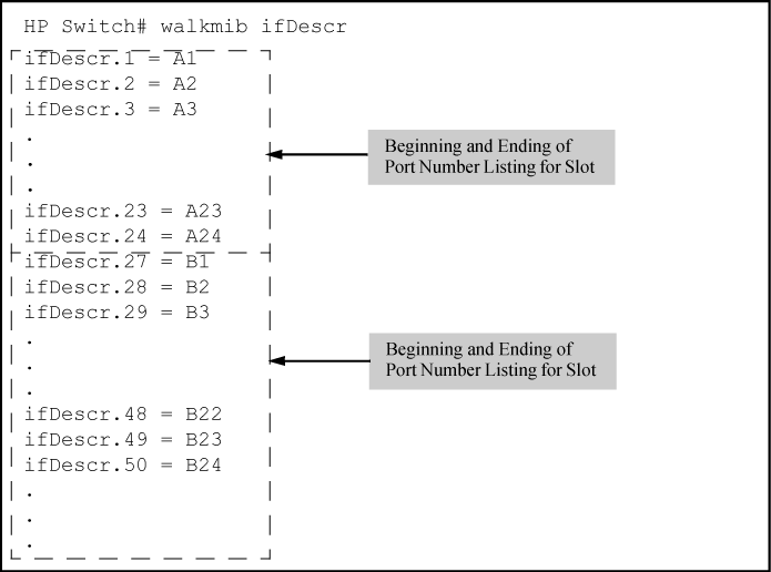
Enabling topology change notification on a switch port and then connecting or disconnecting an LLDP-MED endpoint on that port causes the switch to send an SNMP trap to notify the designated management stations. The port number included in the trap corresponds to the internal number the switch maintains for the designated port, and not the port's external (slot/number) identity. To match the port's external slot/number to the internal port number appearing in an SNMP trap, use the walkmib ifDescr command, as shown in Matching internal port numbers to external slot/port numbers.
Syntax
show lldp info remote-device<PORT-LIST>
Without the <PORT-LIST>
Multiple devices listed for a single port indicates that such devices are connected to the switch through a hub.
Discovering the same device on multiple ports indicates that the remote device may be connected to the switch in one of the following ways:
-
Through different VLANS using separate links. (This applies to switches that use the same MAC address for all configured VLANs.)
-
Through different links using the same VLAN. (In this case, spanning-tree should be invoked to prevent a network topology loop. Note that LLDP packets travel on links that spanning-tree blocks for other traffic types.)
With the <PORT-LIST>
For descriptions of the various types of information displayed by these commands, see Table 6-4.
Examples
A global listing of discovered devices
(HP_Switch_name#) show lldp info remote

 LLDP Remote Devices Information

  LocalPort | ChassisId                 PortId PortDescr SysName
  --------- + ------------------------- ------ --------- -------------
  1         | 00 11 85 35 3b 80         6      6         HP Switch 3500yl
  2         | 00 11 85 cf 66 60         8      8         HP Switch 3500yl