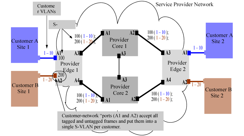
This configuration example uses four HP switches to establish a QinQ tunnel through the provider network.
The design parameters are as follows:
At the end of the configuration, the following settings will apply:
-
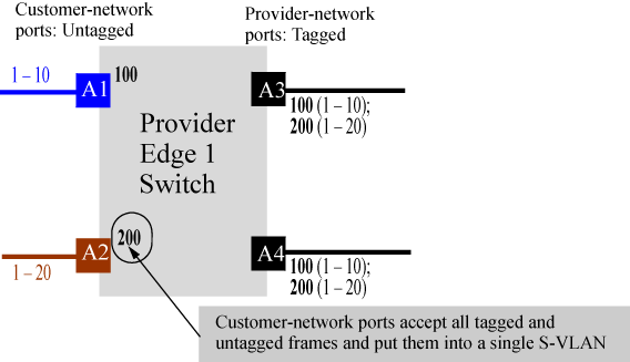
All customer A site traffic received on port A1 will be associated with S-VLAN 100. This is independent of the C-VLAN tag information that the customer frames may carry.
-
All customer B Site 1 traffic will be associated with S-VLAN 200 and be switched out to the core (uplinks A3, A4) with the S-VLAN tag-id of 200.
-
The frame size will increase by 4 since ports A3 and A4 are tagged members of S-VLAN 100 and 200.
To configure the switch, follow these steps:
-
Edge l(config)#: qinq svlan tag-type 88a8
-
Reboot the box with the configuration saved to transfer into svlan bridge mode.
![[NOTE: ]](images/note.gif)
NOTE: A reboot is required for the QinQ enable command to take effect.
-
Configure S-VLANs and ports connected to the customer network.
Edge1(config)#: svlan 100
Edge1(svlan-100)#: untagged A1
Edge1(svlan-100)#: exit
Edge1(config)#: int A1 qinq port-type customer-network
Edge1(config)#: svlan 200
Edge1(svlan-200)#: untagged A2
Edge1(svlan-200)#: exit
Edge1(config)#: int A2 qinq port-type customer-network
NOTE: Customer A is assigned S-VLAN 100 and customer B is assigned S-VLAN 200. However, the same customer can be associated with more than one SVLAN. Also, interfaces A1 and A2 are configured as customer network ports because they are linked to customer bridges.
-
Configure the provider ports leading to the core of the provider network.
Edge1(config)#: svlan 100 tagged A3, A4
Edge1(config)#: svlan 200 tagged A3, A4
Edge1(config)#: interface A3,A4 qinq port-type provider-network
The configuration details for the Edge 2 switch mirrors the configuration for the Edge 1 switch. All customer traffic received on port A1 from customer A's site 2 will be associated with S-VLAN 100. Similarly, all customer B's site 2 traffic will be associated with S-VLAN 200.
To configure the switch, follow these steps:
-
Edge 2(config)#: qinq svlan tag-type 88a8
-
Reboot the box with the configuration saved to transfer into S-VLAN bridge mode.
-
Configure S-VLANs and customer ports connected to the customer network.
Edge2(config)#: svlan 100
Edge2(svlan-100)#: untagged A1
Edge2(svlan-100)#: exit
Edge2(config)#: int A1 qinq port-type customer-network
Edge2(config)#: svlan 200
Edge2(svlan-200)#: untagged A2
Edge2(svlan-200)#: exit
Edge2(config)#: int A2 qinq port-type customer-network
-
Configure the provider ports leading to the core of the provider network.
Edge1(config)#: svlan 100 tagged A3, A4
Edge1(config)#: svlan 200 tagged A3, A4
Edge1(config)#: interface A3,A4 qinq port-type provider-network
To configure the Core 1 switch:
-
Core l(config)#: qinq svlan tag-type 88a8
-
Reboot the box with the configuration saved to transfer into svlan bridge mode.
-
Configure S-VLANs and port assignments.
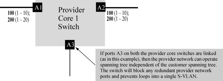
Core 1(config)#: svlan 100
Core 1(svlan-100)#: tagged A1, A2
Core 1(svlan-100)#: exit
Core 1(config)#: svlan 200
Core 1(svlan-200)#: tagged A1, A2
Core 1(svlan-200)#: exit
Core 1(config)#: interface A1,A2 qinq port-type provider-network
|
|
|
|
|
NOTE: The S-VLAN configuration for the core devices is based on what VLANs the edge devices (Edge 1 and 2) can send. Per the 802.1ad specification, all ports carrying customer traffic will be tagged on the VLAN that the port carries customer frames on. |
|
|
To configure the Core 2 switch:
-
Core 2(config)#: qinq svlan tag-type 88a8
-
Reboot the box with the configuration saved to transfer into svlan bridge mode.
-
Configure S-VLANs and port assignments.
Core 2(config)#: svlan 100
Core 2(svlan-100)#: tagged A1, A2
Core 2(svlan-100)#: exit
Core 2(config)#: svlan 200
Core 2(svlan-100)#: tagged A1, A2
Core 2(svlan-100)#: exit
Core 2(config)#: interface A1,A2 qinq port-type provider-network
After the edge and core switch configurations are completed, QinQ operations can begin. To verify operations, it should be possible to assign IP-addresses to customer A or B devices in site 1 and site 2 and ping them. If everything has been configured correctly, traffic will flow through the provider network cloud and reach the other site seamlessly.