|
|
|
![[NOTE: ]](images/note.gif) |
NOTE: All commands previously in the Summary of commands table are indexed under the entry Command syntax. |
|
|
This chapter describes how to enable QinQ operations on the switch and how to configure provider bridge S-VLANs and port assignments.
The IEEE 802.1ad specification, commonly known as QinQ or provider bridging, extends the IEEE 802.1Q standard by providing for a second tier of VLANs in a bridged network. The general purpose of QinQ is to allow frames from multiple customers to be forwarded (or tunneled) through another topology (provider network) using service VLANs or S-VLANs. The provider bridge, which may comprise multiple devices in the service provider domain, looks like a simple bridge port to the customer's traffic and maintains the customer's VLANs.
QinQ network diagram shows a sample QinQ topology and use model. Customer A has LANs spread across multiple site locations and may want to link them together in a single logical LAN. To do this, the customer could have a cable laid out for the entire distance interconnecting the three sites. A more cost-effective and scalable alternative, however, would be to tunnel frames through the provider's network to interconnect all the sites subscribing to the service. This solution can be delivered using QinQ.
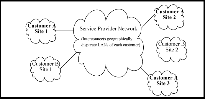
Under QinQ, the provider network operates on a different VLAN space, independent of the VLANs that are used in the customer network.
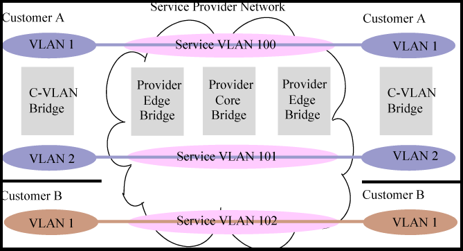
Customer VLANs (referred to as C-VLANs by the IEEE 802.1ad specification) are not used to make any forwarding decisions inside the provider network where customer frames get assigned to service VLANs (S-VLANs). Inside the provider cloud, frames are forwarded based on the S-VLAN tag only, while the C-VLAN tag remains shielded during data transmission. The S-VLAN tag is removed when the frame exits the provider network, restoring the original customer frame.
-
Increases the VLAN space in a provider network or enterprise backbone.
-
Reduces the number of VLANs that a provider needs to support within the provider network for the same number of customers.
-
Enables customers to plan their own VLAN IDs, without running into conflicts with service provider VLAN IDs.
-
Provides a simple Layer 2VPN solution for small-sized MANs (Metropolitan Area Networks) or intranets.
-
Provides for customer traffic isolation at Layer 2 within a Service Provider network.