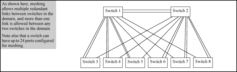
This is a group of meshed switch ports exchanging meshing protocol packets. Paths between these ports can have multiple redundant links without creating broadcast storms.
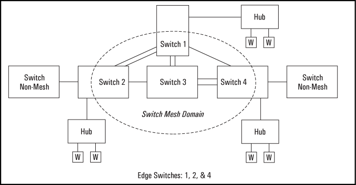
This is a switch that has some ports in the switch meshing domain and some ports outside of the domain. (See A switch mesh domain in a network.)
-
A meshed switch can have some ports in the meshed domain and other ports outside the meshed domain. That is, ports within the meshed domain must be configured for meshing, while ports outside the meshed domain must not be configured for meshing.
-
On any switch, all meshed ports belong to the same mesh domain.
-
Up to five inter-switch, meshed hops are allowed in the path connecting two nodes through a switch mesh domain. A path of six or more meshed hops between two nodes is unusable. However, in most mesh topologies, there would normally be a shorter path available, and paths of five hops or fewer through the same mesh will continue to operate.
-
Other sources of traffic between meshed switch links are not allowed.
-
If the switch has multiple static VLANs and you configure a port for meshing, the port becomes a tagged member of all such VLANs . If you remove a port from meshing, it becomes an untagged member of only the default VLAN.
-
A port configured as a member of a static trunk (LACP or Trunk) cannot also be configured for meshing.
-
If a port belongs to a dynamic LACP trunk and you impose meshing on the port, it automatically ceases to be a member of the dynamic trunk.
-
Meshing is not supported on ports configured with 802.1X access control.
-
On a port configured for meshing, if you subsequently remove meshing from the port's configuration and reboot the switch, the port returns to its default configuration. (It does not revert to any non-default configuration it had before being configured for meshing).
-
In a given mesh domain, switches in the same product family must run the same switch software version. For example, if you update the software version on one 8212zl switch, then you must update the software version on any other 8212zl switch in the mesh. HP recommends that you always use the most recent software version available for the switches in your network.
-
The spanningtree configuration must be the same for all switches in the mesh (enabled or disabled). If spanning tree is enabled in the mesh, it must be the same version on all switches in the mesh: 802.1D, 802.1w, or 802.1s.
-
If a switch in the mesh has GVRP enabled, then all switches in the mesh must have GVRP enabled. Otherwise, traffic on a dynamic VLAN may not pass through the mesh.
If a switch in the mesh has a particular static VLAN configured, then all switches in the mesh must have that static VLAN configured.
-
If a switch in the mesh has IGMP enabled, then all switches in the mesh must have IGMP enabled.
-
If a switch in the mesh has LLDP enabled, then all switches in the mesh must have LLDP enabled.
-
After adding or removing a port from the mesh, you must save the current configuration and reboot the switch in order for the change to take effect.
-
Dynamic IP Lockdown and Virus Throttling should not be activated on mesh ports. These are security features for edge ports and mesh ports are not edge ports.
-
DHCP Snooping and ARP protection are enabled through VLANs. Mesh ports belong to all VLANs, so if these security features are enabled on a switch that has mesh ports, the mesh ports must be configured as “trusted” ports because meshing may move the port of a MAC address in the mesh based on the least cost path.
-
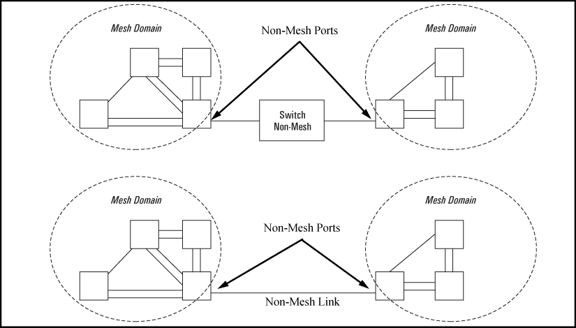
Multiple meshed domains require separation by either a non-meshed switch or a non-meshed link. For example:
-
If GVRP is enabled, meshed ports in a switch become members of any dynamic VLANs created in the switch in the same way that they would if meshing was not configured in the switch.
When a meshed port detects a non-meshed port on the opposite end of a point-to-point connection, the link will be blocked. Thus, as you bring up switch meshing on various switches, you may temporarily experience blocked ports where meshed links should be running. These conditions should clear themselves after all switches in the mesh have been configured for meshing and their switches rebooted. To reduce the effect of blocked ports during bring-up, configure meshing and reboot the switches before installing the meshed switches in the network. Also, since adding (or removing) a meshed port requires a switch reboot to implement, you can avoid repeated system disruptions by waiting to implement the mesh until you have finished configuring meshing on all ports in your intended mesh domain.
In a switch mesh domain traffic is distributed across the available paths with an effort to keep latency the same from path to path. The path selected at any time for a connection between a source node and a destination node is based on these latency and throughput cost factors:
-
Outbound queue depth, or the current outbound load factor for any given outbound port in a possible path
-
Port speed, such as 10Mbps versus 100Mbps; full-duplex or half-duplex
-
Inbound queue depth, or how busy a destination switch is in a possible path
-
Increased packet drops, indicating an overloaded port or switch
Pathshaving a lower cost will have more traffic added than those having a higher cost. Alternate paths and cost information is discovered periodically and communicated to the switches in the mesh domain. This information is used to assign traffic paths between devices that are newly active on the mesh. This means that after an assigned path between two devices has timed out, new traffic between the same two devices may take a different path than previously used.
Broadcast and multicast packets will always use the same path between the source and destination edge switches unless link failures create the need to select new paths. (Broadcast and multicast traffic entering the mesh from different edge switches are likely to take different paths.) When an edge switch receives a broadcast from a non-mesh port, it floods the broadcast out all its other non-mesh ports, but sends the broadcast out only those ports in the mesh that represent the path from that edge switch through the mesh domain. (Only one copy of the broadcast packet gets to each edge switch for broadcast out of its non-meshed ports. This helps to keep the latency for these packets to each switch as low as possible.)
Any mesh switches that are not edge switches will flood the broadcast packets only through ports (paths) that link to separate edge switches in the controlled broadcast tree. The edge switches that receive the broadcast will flood the broadcast out all non-meshed ports. Some variations on broadcast/multicast traffic patterns, including the situation where multiple VLANs are configured and a broadcast path through the mesh domain leads only to ports that are in the same VLAN as the device originating the broadcast.
A meshed switch receiving a unicast packet with an unknown destination does not flood the packet onto the mesh. Instead, the switch sends a query on the mesh to learn the location of the unicast destination. The meshed switches then send 802.2 test packets through their non-meshed ports. After the unicast destination is found and learned by the mesh, subsequent packets having the same destination address will be forwarded. By increasing the MAC Age Time you can cause the switch address table to retain device addresses longer. Because the switches in a mesh exchange address information, this will help to decrease the number of unicast packets with unknown destinations, which improves latency within the switch mesh. Also, in an IP environment, HP Networking recommends that you configure IP addresses on meshed switches. This makes the discovery mechanism more robust, which contributes to decreased latency. For more on mac-age-time, see the Basic Operations Guide for your switch.
|
|
|
![[NOTE: ]](images/note.gif) |
NOTE: Switch meshing cannot run concurrently with RPVST+. |
|
|
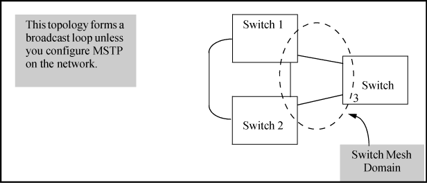
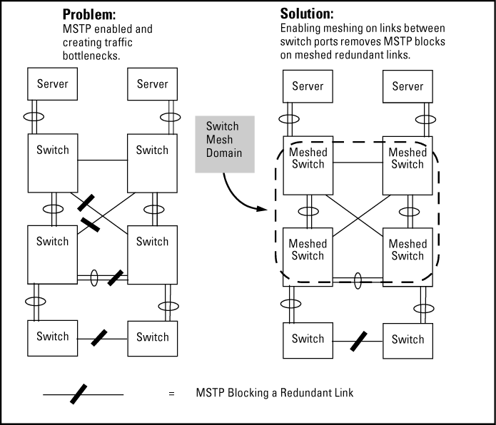
Using MSTP with several switches and no switch meshing configured can result in unnecessarily blocking links and reducing available bandwidth. For example:
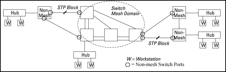
Connecting a switch mesh domain to non-meshed devices
If you are going to use spanning tree in a switch mesh, all switches in the mesh should be configured with the same type of spanning tree: 802.1d/STP, 802.1w/RSTP, or 802.1s/MSTP. spanning tree interprets a meshed domain as a single link. However, on edge switches in the domain, MSTP will manage non-meshed redundant links from other devices. For example:
|
|
|
|
|
NOTE: When using MSTP and interconnecting switches covered in this guide in a mesh with switches that are not in the mesh, all the non-mesh switch ports should have the |
|
|
Interconnecting switch mesh domains with redundant links
MSTP should be configured on non-mesh devices that use redundant links to interconnect with other devices or with multiple switch mesh domains. For example:
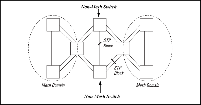
In the above case of multiple switch meshes linked with redundant trunks, there is the possibility that spanning tree will temporarily block a mesh link. This is because it is possible for spanning tree to interpret the cost on an external trunked link to be less than the cost on a meshed link. However, if this condition occurs, the meshed switch that has a blocked link will automatically increase the cost on the external (non-meshed) link to the point where spanning tree will block the external link and unblock the meshed link. This process typically resolves itself in approximately 30 seconds.
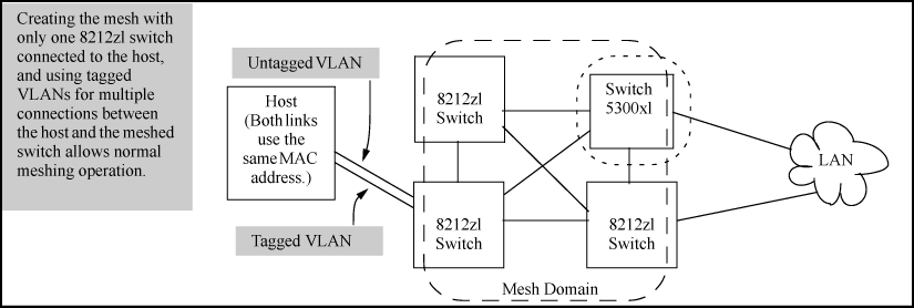
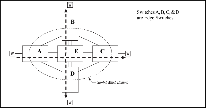
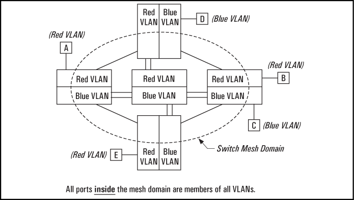
In a network having a switch mesh domain and multiple static VLANs configured, all static VLANs must be configured on each meshed switch, even if no ports on the switch are assigned to any VLAN. (The switch mesh is a member of all static VLANs configured on the switches in the mesh.)
When static VLANs are configured, the mesh is seen as a single entity by each VLAN. All ports in the mesh domain are members of all VLANs and can be used to forward traffic for any VLAN. However, the non-mesh ports on edge switches that allow traffic to move between the mesh and non-meshed devices belong to specific VLANs and do not allow packets originating in a specific VLAN to enter non-meshed devices that do not belong to that same VLAN. (It is necessary to use a router to communicate between VLANs.) For example, in VLAN operation with a switch mesh domain, traffic from host A entering the switch mesh can only exit the mesh at the port for hosts B and E. Traffic from host A for any other host (such as C or D) will be dropped because only hosts B and E are in the same VLAN as host A.
If GVRP is enabled, meshed ports in a switch become members of any dynamic VLANs created in the switch in the same way that they would if meshing was not configured in the switch.
If you enable jumbo traffic on any VLAN, then all meshed ports on the switch will be enabled to support jumbo traffic. (On a given meshed switch, every meshed port becomes a member of every VLAN configured on the switch.) If a port in a meshed domain does not belong to any VLANs configured to support jumbo traffic, then the port drops any jumbo packets it receives from other devices. In this regard, if a mesh domain includes any HP 8212zl switches, 6200yl switches, Series 5400zl switches, Series 3500yl switches, Series 3400cl or Series 6400cl switches that are configured to support jumbo traffic, only these switches can transmit and receive jumbo packets. Other switch models in the mesh will drop jumbo packets as they are not supported by those switches. See the Management and Configuration Guide for your switch.
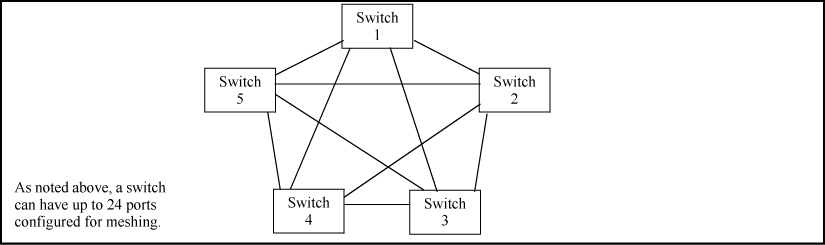
Mesh performance can be enhanced by using mesh designs that are as small and compact as possible while still meeting the network design requirements. The following are limits on the design of meshes and have not changed:
Mesh performance can be optimized by keeping the number of switches and the number of possible paths between any two nodes as small as possible. As mesh complexity grows, the overhead associated with dynamically calculating and updating the cost of all of the possible paths between nodes grows exponentially. Cost discovery packets are sent out by each switch in the mesh every 30 seconds and are flooded to all mesh ports. Return packets include a cost metric based on inbound and outbound queue depth, port speed, number of dropped packets, and so on. Also, as mesh complexity grows, the number of hops over which a downed link has to be reported may increase, thereby increasing the reconvergence time.
The simplest design is the two-tier design because the number of possible paths between any two nodes is kept low and any bad link would have to be communicated only to its neighbor switch.
Other factors affecting the performance of mesh networks include the number of destination addresses that have to be maintained, and the overall traffic levels and patterns. However, a conservative approach when designing new mesh implementations is to use the two-tier design and limit the mesh domain to eight switches where possible.
Other factors affecting the performance of mesh networks include the number of destination addresses that have to be maintained, and the overall traffic levels and patterns. However, a conservative approach when designing new mesh implementations is to use the two-tier design and limit the mesh domain to eight switches where possible.
See the Multicast and Routing Guide for your switch.
-
The VRRP configuration parameter
preempt-delay-timeshould be set to at least 60 for each virtual router. This is because meshing is a distributed protocol that takes some time to stabilize when a new switch enters the mesh. A failing switch will be treated as new when it reenters the mesh. Since meshing is an L2 protocol, it must be stable before L3 VRRP can become active. The preempt-delay-time is only observed in the case where an already active VRRP router exists. This will allow the existing router to continue serving its role until the preferred router, owner or higher priority backup, is truly ready to take over. -
The VRRP configuration parameter
nonstopwill not be configurable when VRRP is configured within a mesh. This is because the VRRPnonstopconfiguration attempts to make VRRP hitless in the case of a failed management module. Meshing, however, is not hitless in this case. Having the nonstop parameter set will cause the VRRP virtual router to ignore thepreempt-delay-timeand will have the virtual router attempt to become active before meshing is ready. This will result in a potential 30 or more second routed traffic gap while meshing becomes stable. -
For best network resiliency during a VRRP failover event, all switches in the mesh domain must be running x.15.09 or later version of the switch software. This is because changes in versions x.15.09 and later allow a VRRP virtual router MAC address to move from the master to the backup without being blocked by meshing on connected switches in the mesh.
-
Using 5300 series switches in the same mesh domain that implements VRRP with concurrent meshing and routing is not recommended.
|
All switches in the mesh domain, including edge switches, must support the HP witch meshing protocol. |
|
To connect two separate switch meshing domains, you must use non-meshed ports. (The non-meshed link can be a porttrunk or a single link.) See Multiple meshed domains separated by a non-mesh switch or a non-mesh link. |
|
If a network monitor port is configured, broadcast packets may be duplicated on that port if more than one port is being monitored and switch meshing is enabled. |
For additional information on troubleshooting meshing problems, see the Basic Operations Guide for your switch.