Concurrent meshing and routing is supported 8200/5400 v2 module, 3800, and later products.
| Module | Description |
|---|---|
| J9534A | 24-Port Gig-T PoE+ v2 zl Module |
| J9535A | 20-Port Gig-T PoE+ / 4-port SFP v2 zl Module |
| J9536A | 20-Port Gig-T PoE+ / 2-port 10-GbE SFP+ v2 zl Module |
| J9537A | 24-Port SFP v2 zl Module |
| J9538A | 8-Port 10-GbE SFP+ v2 zl Module |
| J9547A | 24-Port 10/100 PoE+ v2 zl Module |
| J9548A | 20-Port Gig-T / 2-port 10-GbE SFP+ v2 zl Module |
| J9549A | 20-Port Gig-T / 4-port SFP v2 zl Module |
| J9550A | 24-Port Gig-T v2 zl Module |
| J9637A | 12-Port SFP / 12-port PoE+ v2 zl Module |
|
|
|
![[NOTE: ]](images/note.gif) |
NOTE: Since concurrent meshing and routing is only supported on V2 modules, the |
|
|
Meshing and routing can be configured simultaneously. A packet can be routed into a mesh, or be switched through a mesh and then routed. Two routers can be connected by mesh links, which offers additional network topologies between routers and switches. Concurrent meshing and routing makes it possible to implement meshing throughout a broadcast domain without the need for additional switches or the use of another Layer 2 technology such as Spanning Tree to connect meshing domains with routing switches.
It is important to remember that meshing provides Layer 2 load balancing only; two traffic streams going to the same router will take the same path through the mesh as the traffic is going to the same MAC address.
|
|
|
|
|
NOTE: The mesh port on a switch is tagged on all VLANs on that switch. HP recommends that every meshed switch have the same VLANs, whether they are used or not. |
|
|
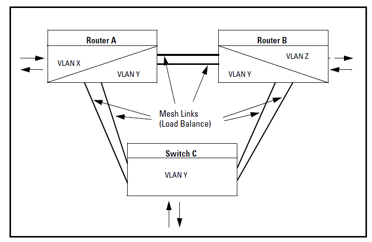
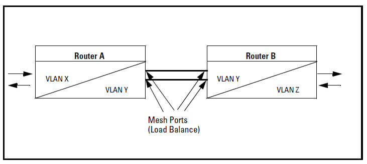
When Router A has no ports belonging to VLAN Z, the packets arriving on Router A’s non-mesh ports at VLAN X can be routed to VLAN Y, travel through the mesh, and arrive at Router B. After that they can be routed from VLAN Y to VLAN Z.
Switches and routers can be meshed together to create more complex local area networks with many redundant mesh links. Load balancing utilizes redundant links in the mesh to deliver traffic efficiently.
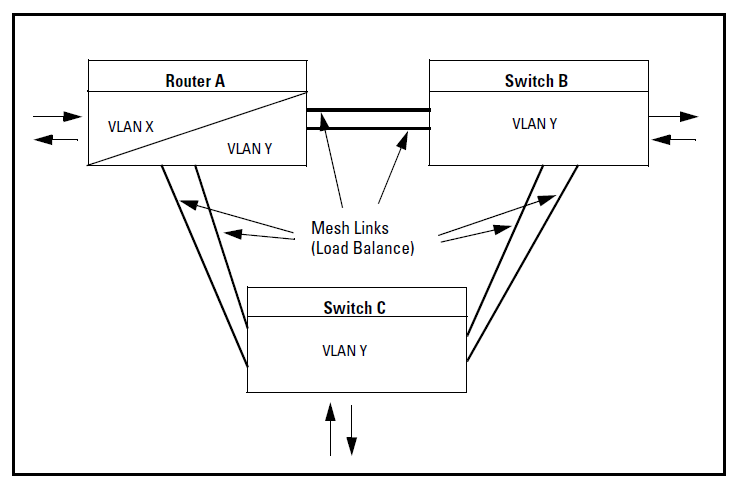
Packets arriving at Router A’s non-mesh port at VLAN X may be routed to VLAN Y, then switched through the mesh to a host connected to Switch B. Depending on the cost of the link between Router A and Switch B, the packets may be delivered to Switch C, and then forwarded to Switch B if that mesh path is less costly.
Packets arriving at the non-mesh ports for Switch B and Switch C may need to reach Router A. These packets are delivered through the mesh with the least mesh path cost.
The following example shows two routers and one switch that are meshed together. Packets arriving at the non-mesh ports on VLAN X on Router A may be routed to VLAN Y. Load balancing determines which port Router A should send the packets to in order for the packets to reach Router B.