Below are the test and verification methods used to verify convergence results. Three tests were performed:
This test verifies when an active link fails during an FTP download, the network converges quickly enough that the FTP transfer succeeds. The following steps outline the test procedure followed.
-
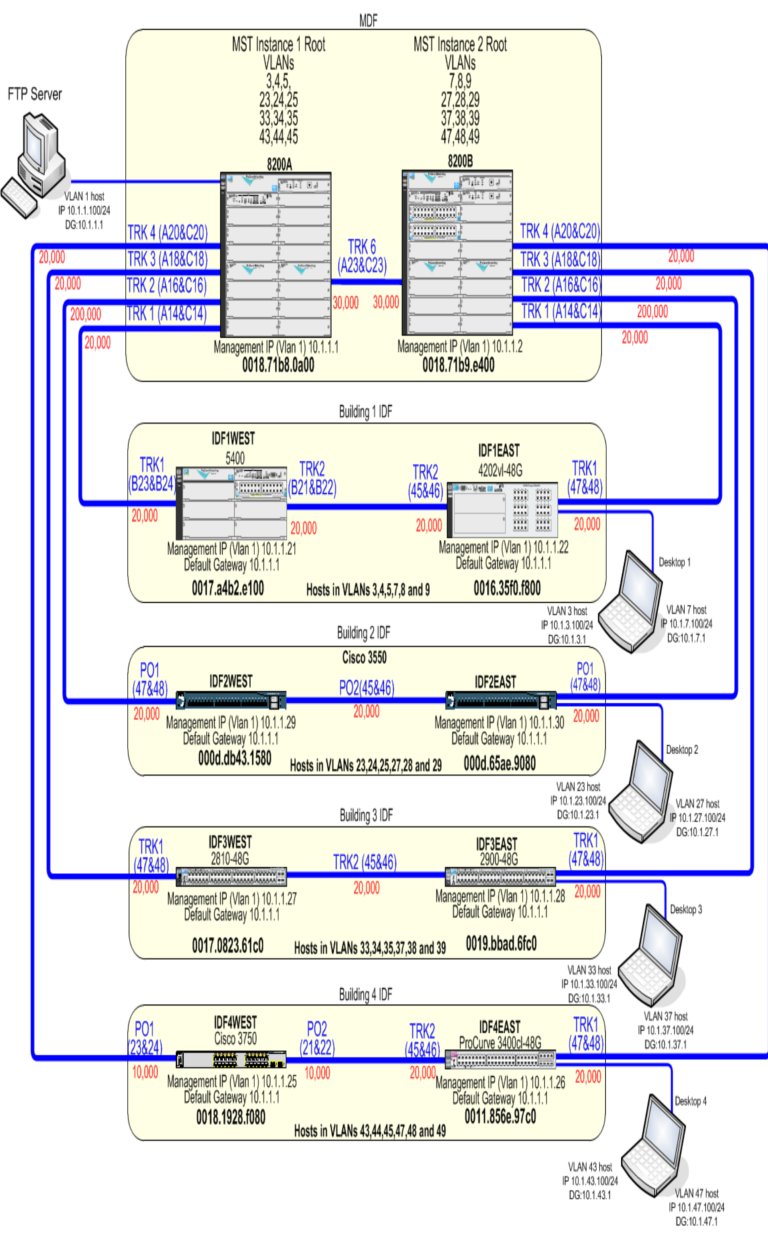
Setup an FTP server on 8200A on port A1, on VLAN 1 with IP address 10.1.1.100.
-
Configure a port on one of the switches in IDF 1 for a VLAN (VLAN 3) on Instance 1.
-
Connect the client to port with IP address 10.1.3.100 and gateway 10.1.3.1.
-
Start an FTP download on a large file , for example no smaller than 800 MB.
-
Break the active link for Instance 1 immediately after initiating the FTP transfer to simulate a link failure. For VLAN 3 on switch IDF1EAST the LAG between IDF1WEST and the 8200A was broken.
-
Log the time from when the transfer rate starts to decrease until transfer rate starts to increase.
-
For Instance 2 VLAN 7 was used. The client was configured with IP 10.1.7.100 and gateway 10.1.7.1. Break active link between IDF1EAST and 8200B.
The active LAG was disconnected. The transfer rate began to decrease quickly. After approximately 4 seconds the transfer rate started to increase again and the FTP transfer was successful for both instances.
This test verifies that when an active link fails, the redundant link becomes active. Capture how much time it takes to converge. Below outlines the test procedure followed:
It took approximately 3 seconds for the convergence to complete for both Instances. One ping was lost. Below is a screen capture of the test.
C:\Documents and Settings\Owner>ping 10.1.3.1 -t
Pinging 10.1.3.1 with 32 bytes of data:
Reply from 10.1.3.1: bytes=32 time=2ms TTL=255
Reply from 10.1.3.1: bytes=32 time=6ms TTL=255
Reply from 10.1.3.1: bytes=32 time=988ms TTL=255
Reply from 10.1.3.1: bytes=32 time=10ms TTL=255
Reply from 10.1.3.1: bytes=32 time=10ms TTL=255
This test simulates an 8200 chassis failure and validates network convergence recovery time.
-
Setup an FTP server on switch #8200B on port A1. Setup an FTP server on VLAN 1 with the IP address 10.1.1.30.
-
Configure a port on one of the switches in IDF 1 for a VLAN (VLAN 3) on Instance 1.
-
Connect client to port with IP address 10.1.3.100 and gateway 10.1.3.1.
-
Log how much time between when the FTP transfer rate starts to decrease until transfer rate starts to increase.
-
For Instance 2 VLAN 7 was used. The client was configured with IP 10.1.7.100 and gateway 10.1.7.1. Shut down 8200B.
The transfer rate began to decrease quickly once 8200A lost power. After approximately 3 seconds the transfer rate started to increase again and the FTP transfer was successful for both core failure tests.
MSTP and VRRP provide an excellent, highly available network solution with layer 2 and layer 3 redundancies combined with the ability to load balance network traffic, optimizing network performance. When configuring MSTP and VRRP, be sure to follow the configuration checklist. Careful attention is required to correctly configure MSTP and VRRP; however, the benefits are worth the effort. Fast convergence times are achieved if a link or switch failure occurs, ensuring maximum network uptime.