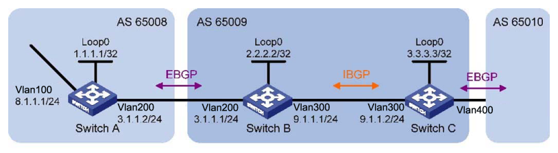
In the following network, run eBGP between Switch A and Switch B and iBGP between Switch B and Switch C so that Switch C can access the network 8.1.1.0/24 connected to Router A.
-
-
To prevent route flapping caused by port state changes, this example uses loopback interfaces to establish iBGP connections.
-
Because loopback interfaces are virtual interfaces, you need to use the
peer connect-interfacecommand to specify the loopback interface as the source interface for establishing BGP connections. -
Enable OSPF in AS 65009 to ensure that Switch B can communicate with Switch C through loopback interfaces.
HP Switch(config)# router bgp 65009
HP Switch(bgp)# bgp router-id 2.2.2.2
HP Switch(bgp)# neighbor 3.3.3.3 remote-as 65009
HP Switch(bgp)# exit
HP Switch(config)# router ospf
HP Switch(ospf)# enable
HP Switch(ospf)# area 0
HP Switch(ospf)# network 2.2.2.2/32
HP Switch(ospf)# network 9.1.1.1/24
HP Switch(ospf)# exit
HP Switch(config)# vlan 300
HP Switch(vlan-300)# ip ospf
HP Switch(config)# router bgp 65009
HP Switch(bgp)# bgp router-id 3.3.3.3
HP Switch(bgp)# neighbor 2.2.2.2 remote-as 65009
HP Switch(bgp)# neighbor 2.2.2.2 connect-interface loopback 0
HP Switch(bgp)# exit
HP Switch(config)# router ospf
HP Switch(ospf)# enable
HP Switch(ospf)# area 0
HP Switch(ospf)# network 3.3.3.3/32
HP Switch(ospf)# network 9.1.1.0/24
HP Switch(ospf)# exit
HP Switch(config)# vlan 300
HP Switch(vlan-300)# ip ospf
HP Switch(vlan-300)# show ip bgp summary

Peer Information

Remote Address Remote-AS Local-AS State Admin  Status
-------------- --------- -------- ------------ -----
2.2.2.2        65009     65009    Established  Start
The output information shows that Switch C has established an iBGP peer relationship with Switch B.
-
-
-
The eBGP peers, Switch A and Switch B (usually belonging to different carriers), are located in different ASs. Their loopback interfaces are not reachable to each other, so directly connected interfaces are used for establishing BGP sessions.
-
To enable Switch C to access the network 8.1.1.0/24 that is connected directly to Switch A, add network 8.1.1.0/24 to the BGP routing table of Switch A.
HP Switch(config)# router bgp 65008
HP Switch(bgp)# bgp router-id 1.1.1.1
HP Switch(bgp)# neighbor 3.1.1.1 remote-as 65009
HP Switch(bgp)# network 8.1.1.1/24
HP Switch(bgp)# exit
HP Switch(config)# router bgp 65009
HP Switch(bgp)# neighbor 3.1.1.2 remote-as 65008
HP Switch(bgp)# exit
# Show IP bgp peer information on Switch B.
HP Switch(config)# show ip bgp summary

Peer Information

Remote Address Remote-AS Local-AS State        Admin Status
-------------- --------- -------- --------     ------------
2.2.2.2        65009     65009    Established  Start
3.1.1.2        65008     65009    Established  Start
The output shows that Switch B has established an iBGP peer relationship with Switch C and an eBGP peer relationship with Switch A.
# Display the BGP routing table on Switch A.
HP Switch(bgp)# show ip bgp

Local AS : 100
Local Router-id : 20.0.0.1
BGP Table Version : 0
Status codes: * - valid, > - best, i - internal, e -
external, s - stale
Origin codes: i - IGP, e - EGP, ? - incomplete

Network          Nexthop  Metric LocalPref  Weight AsPath
----------------------------------------------------------
*> 8.1.1.0/24                   0            32768    I
*> 8.1.1.0/24     0.0.0.0       0               0     I
# Display the BGP routing table on Switch B.
HP Switch# show ip bgp

Local AS : 100
Local Router-id : 20.0.0.1

BGP Table Version  : 0
Status codes: * - valid, > - best, i - internal, e - external, s - stale

Origin codes: i - IGP, e - EGP, ? - incomplete

Network        Nexthop  Metric LocalPref   Weight AsPath
---------------------------------------------------------
*>e 8.1.1.0/24                0              0    65008i
# Display the BGP routing table on Switch C.
HP Switch(bgp)# show ip bgp

Local AS : 100
Local Router-id : 20.0.0.1

BGP Table Version  : 0
Status codes: * - valid, > - best, i - internal, e - external, s - stale

Origin codes: i - IGP, e - EGP, ? - incomplete

Network         Nexthop    Metric LocalPref Weight AsPath
---------------------------------------------------------
*>i 8.1.1.0/24                  0            0     65008i
![[NOTE: ]](images/note.gif)
NOTE: From the above outputs, you see that Switch A has not learned a route to AS 65009, and Switch C has learned network 8.1.1.0 but the next hop 3.1.1.2 is unreachable, so the route is invalid.
-
-
Redistribute connected routes.
Configure BGP to redistribute direct routes on Switch B, so that Switch A can obtain the route to 9.1.1.0/24 and Switch C can obtain the route to 3.1.1.0/24.
HP Switch(config)# router bgp 65009
HP Switch(bgp)# redistribute connected
# Display the BGP routing table on Switch A.
HP Switch# show ip bgp

Local AS : 65009
Local Router-id : 1.1.1.1

BGP Table Version  : 0
Status codes: * - valid, > - best, i - internal, e - external, s - stale

Origin codes: i - IGP, e - EGP, ? - incomplete

Network         Nexthop    Metric LocalPref Weight AsPath
---------------------------------------------------------
*>e 2.2.2.2/32  3.1.1.1        0             0     65009?
*>e 3.1.1.0/24  3.1.1.1        0             0     65009?
*>e 8.1.1.0/24                 0             0     65008i
*>e 8.1.1.0/24                 0             0     65008i
Two routes 2.2.2.2/32 and 9.1.1.0/24 have been added in Switch A’s routing table.
# Display the BGP routing table on Switch C.
HP Switch(config)# show ip bgp

Local AS : 65009
Local Router-id : 3.3.3.3

BGP Table Version  : 1

Status codes: * - valid, > - best, i - internal, e - external, s - stale

Origin codes: i - IGP, e - EGP, ? - incomplete

Network         Nexthop Metric LocalPref Weight AsPath
-------------------------------------------------------
*>e 2.2.2.2/32   9.1.1.1           0      100     I
*>e 3.1.1.0/24   9.1.1.1           0      100     I
*>e 8.1.1.0/24                     0      0       65008i
*e 9.1.1.0/24                      0      0       65008i
*>e 9.1.1.0/24                     0      0       65008i
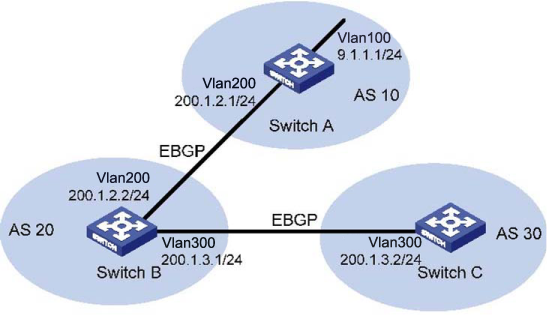
In the following figure, Switch B establishes eBGP connections with Switch A and C. Configure the No_Export community attribute on Switch A so that routes from AS 10 are not advertised by AS 20 to any other AS.
-
HP Switch(config)# router bgp 10
HP Switch(bgp)# bgp router-id 1.1.1.1
HP Switch(bgp)# neighbor 200.1.2.2 remote-as 20
HP Switch(bgp)# network 9.1.1.0/255.255.255.0/8
HP Switch(bgp)# exit
HP Switch(config)# bgp 20
HP Switch(bgp)# bgp router-id 2.2.2.2
HP Switch(bgp)# neighbor 200.1.2.1 remote-as 10
HP Switch(bgp)# neighbor 200.1.3.2 remote-as 30
HP Switch(bgp)# exit
HP Switch(config)# bgp 30
HP Switch(bgp)# bgp router-id 3.3.3.3
HP Switch(bgp)# neighbor 200.1.3.1 remote-as 20
HP Switch(bgp)# exit
# Display the BGP routing table on Switch B.
HP Switch(config)# show ip bgp 9.1.1.0

Local AS : 20 Local Router-id : 2.2.2.2
BGP Table Version  : 3

Network : 9.1.1.0/24       Nexthop         : 200.1.2.1
Peer   : 200.1.2.1        Origin          : igp
Metric : 0                Local Pref      :
Weight : 0                Calc. Local Pref : 100
Valid  : Yes              Type            : external
Stale  : No
Best   : Yes (Only Route Available)
AS-Path : 100
Communities :
Switch B advertised routes to Switch C in AS 30.
# Display the routing table on Switch C.
HP Switch(config)# show ip bgp

Local AS : 30
Local Router-id : 3.3.3.3

BGP Table Version  : 1
Status codes: * - valid, > - best, i - internal, e - external, s - stale

Origin codes: i - IGP, e - EGP, ? - incomplete

Network        Nexthop   Metric LocalPref Weight AsPath
-------------------------------------------------------
*>i 9.1.1.0/24 200.1.3.1      0            100     10i
-
route-map bgp-out permit seq 10
HP Switch(route-map-bgp-out)# set community no-export
HP Switch(route-map-bgp-out)# exit
HP Switch(config)# bgp 10
HP Switch(bgp)# neighbor 200.1.2.2 route-map bgp-out out
# Display the route on Switch B.
HP Switch(config)# show ip bgp 9.1.1.0/24

Local AS : 20 Local Router-id : 2.2.2.2
BGP Table Version  : 3

Network     : 9.1.1.0/24   Nexthop         : 200.1.2.1
Peer       : 200.1.2.1    Origin          : igp Metric     : 0            Local Pref      : Weight
   : 0            Calc. Local Pref : 100
Valid      : Yes          Type            : external
Stale      : No
Best       : Yes (Only Route Available) AS-Path    : 100
Communities: no-export

# Display the routing table on Switch C.
HP Switch# show ip bgp 9.1.1.0/24
The route 9.1.1.0/24 is not available in the routing table of Switch C.
-
HP Switch(config)# router bgp 100
HP Switch(bgp)# bgp router-id 1.1.1.1
HP Switch(bgp)# neighbor 192.1.1.2 remote-as 200
# Add network 1.0.0.0/8 to the BGP routing table.
HP Switch(bgp)# network 1.0.0.0
HP Switch(bgp)# exit
HP Switch(config)# router bgp 200
HP Switch(bgp)# bgp router-id 2.2.2.2
HP Switch(bgp)# neighbor 192.1.1.1 remote-as 100
HP Switch(bgp)# neighbor 193.1.1.1 remote-as 200
HP Switch(bgp)# neighbor 193.1.1.1 next-hop-self
HP Switch(bgp)# exit
HP Switch(config)# router bgp 200
HP Switch(bgp)# bgp router-id 3.3.3.3
HP Switch(bgp)# neighbor 193.1.1.2 remote-as 200
HP Switch(bgp)# neighbor 194.1.1.2 remote-as 200
HP Switch(bgp)# exit
HP Switch(config)# router bgp 200
HP Switch(bgp)# bgp router-id 4.4.4.4
HP Switch(bgp)# neighbor 194.1.1.1 remote-as 200
HP Switch(bgp)# exit
-
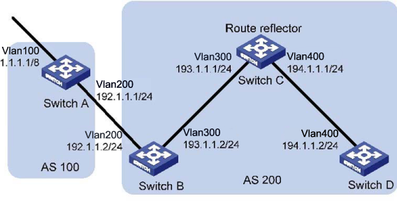
Configure the route reflector.
HP Switch(config)# router bgp 200
HP Switch(bgp)# neighbor 193.1.1.2 route-reflector-client
HP Switch(bgp)# neighbor 194.1.1.2 route-reflector-client
HP Switch(bgp)# exit
-
Verify the above configuration.
# Display the BGP routing table on Switch B.
HP Switch(config)# show ip bgp

Local AS : 200
Local Router-id : 200.1.2.2

BGP Table Version  : 1
Status codes: * - valid, > - best, i - internal, e - external, s - stale
Origin codes: i - IGP, e - EGP, ? - incomplete

Network          Nexthop     Metric LocalPref Weight  AsPath
------------------------------------------------------------
*>i 1.0.0.0/24   200.1.3.1       0              0     100i
# Display the BGP routing table on Switch D.
HP Switch(config)# show ip bgp

Local AS : 200
Local Router-id : 200.1.2.2

BGP Table Version  : 1
Status codes: * - valid, > - best, i - internal, e - external, s - stale
Origin codes: i - IGP, e - EGP, ? - incomplete

Network        Nexthop     Metric LocalPref Weight AsPath
-------------------------------------------------------
*>e 1.0.0.0/24 200.1.3.1        0           100    100i
-
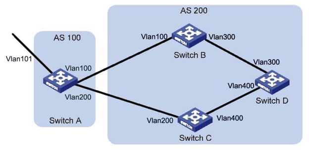
In the figure below, all switches run BGP. eBGP connections are between Switch A and Switch B, and between Switch A and Switch C. iBGP connections are between Switch B and Switch D, and between Switch C and Switch D.
-
Configure the routing policies. Switch D should use the route 1.0.0.0/8 from Switch C as the optimal route.
-
Configure OSPF on Switch B, C, and D.
HP Switch(config)# router ospf
HP Switch(ospf)# area 0
HP Switch(ospf)# network 192.1.1.0/ 0.0.0.255
HP Switch(ospf)# network 194.1.1.0/ 0.0.0.255
HP Switch(ospf)# exit
HP Switch(config)# router ospf
HP Switch(ospf)# enable
HP Switch(ospf)# area 0
HP Switch(ospf)# network 193.1.1.0/ 0.0.0.255
HP Switch(ospf)# network 195.1.1.0/ 0.0.0.255
HP Switch(ospf)# exit
HP Switch(config)# router ospf
HP Switch(ospf)# enable
HP Switch(ospf)# area 0
HP Switch(ospf)# network 194.1.1.0/ 0.0.0.255
HP Switch(ospf)# network 195.1.1.0/ 0.0.0.255
HP Switch(ospf)# exit
-
HP Switch(config)# router bgp 100
HP Switch(bgp)# neighbor 192.1.1.2 remote-as 200
HP Switch(bgp)# neighbor 193.1.1.2 remote-as 200
# Add network 1.0.0.0/8 to the BGP routing table on Switch A.
HP Switch(bgp)# network 1.0.0.0/8
HP Switch(bgp)# exit
HP Switch(config)# router bgp 200
HP Switch(bgp)# neighbor 192.1.1.1 remote-as 100
HP Switch(bgp)# neighbor 194.1.1.1 remote-as 200
HP Switch(bgp)# exit
HP Switch(config)# router bgp 200
HP Switch(bgp)# neighbor 193.1.1.1 remote-as 100
HP Switch(bgp)# neighbor 195.1.1.1 remote-as 200
HP Switch(bgp)# exit
HP Switch(config)# router bgp 200
HP Switch(bgp)# neighbor 194.1.1.2 remote-as 200
HP Switch(bgp)# neighbor 195.1.1.2 remote-as 200
HP Switch(bgp)# exit
-
Configure attributes for route 1.0.0.0/8, making Switch D give priority to the route learned from Switch C.
# Configure a higher MED value for the route 1.0.0.0/8 advertised from Switch A to peer 192.1.1.2.
# Define a prefix-list to permit route 1.0.0.0/8.
HP Switch(config)# ip prefix-list pl_1 permit 1.0.0.0/24
# Define two routing policies, apply_med_50, which sets the MED for route 1.0.0.0/8 to 50, and apply_med_100, which sets the MED for route 1.0.0.0/8 to 100.
HP Switch(config)# route-map apply_med_50 permit
HP Switch(route-map-apply_med_50)# match ip address prefix-list pl_1
HP Switch(route policy)# set metric 50
HP Switch(route policy)route-map apply_med_50 permit seq 20
HP Switch(route policy)# exit

HP Switch(config)# route-map apply_med_100 permit
HP Switch(route policy)# match ip address prefix-list pl_1
HP Switch(route policy)# set metric 100
HP Switch(route policy)# route-map apply_med_100 permit seq 20
HP Switch(route policy)# exit
# Apply routing policy apply_med_50 to the route advertised to peer 193.1.1.2 (Switch C), and apply_med_100 to the route advertised to peer 192.1.1.2 (Switch B.)
HP Switch(config)# bgp 100
HP Switch(bgp)# neighbor 193.1.1.2 route-map apply_med_50 out
HP Switch(bgp)# neighbor 192.1.1.2 route-policy apply_med_100 out
HP Switch(bgp)# exit
# Display the BGP routing table on Switch D.
HP Switch(config)# show ip bgp

Local AS : 100
Local Router-id : 194.1.1.1

BGP Table Version  : 1

Status codes: * - valid, > - best, i - internal, e - external, s - stale
Origin codes: i - IGP, e - EGP, ? - incomplete

Network        Nexthop    Metric LocalPref Weight AsPath
-------------------------------------------------------
*>e 1.0.0.0/24 194.1.1.2      50            0     100i

*>e 1.0.0.0/24 195.1.1.2     100            0     100i
You can ensure that route 1.0.0.0/8 is the optimal route. Configure different local preferences on Switch B and C for route 1.0.0.0/ 8, making Switch D give priority to the route from Switch C.
# Define an ip prefix-list on Router C, permitting route 1.0.0.0/8.
HP Switch(config)# ip prefix-list pl_1 permit 1.0.0.0/8
# Configure a routing policy named localpref on Switch C, setting the local preference of route 1.0.0.0/8 to 200 (the default is 100.)
HP Switch(config)# route-map localpref permit seq 10
HP Switch(route-policy)# match ip address prefix-list pl_1
HP Switch(route-policy)# set local-preference 200
HP Switch(route-policy)# route-map localpref permit seq 20
# Apply routing policy localpref to routes from peer 193.1.1.1.
HP Switch(config)# router bgp 200
HP Switch(bgp)# neighbor 193.1.1.1 route-map localpref in
HP Switch(bgp)# exit
# Display the routing table on Switch D.
HP Switch(config)# show ip bgp

Local AS : 100
Local Router-id : 194.1.1.1

BGP Table Version  : 1

Status codes: * - valid, > - best, i - internal, e - external, s - stale
Origin codes: i - IGP, e - EGP, ? - incomplete

Network       Nexthop   Metric LocalPref Weight AsPath
-------------------------------------------------------
*>e 1.0.0.0/24 200.1.3.1    200            0     100i
* i 1.0.0.0/24              100            0     100i
You can see that route 1.0.0.0/8 from Switch D to Switch C is the optimal route.
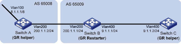
In the following figure, all switches are BGP switches. There is a eBGP connection between Switch A and Switch B. Switch B and Switch C are connected over an iBGP connection. Enable GR for BGP so that the communication between Switch A and Switch C is not affected when an active/ standby main board switchover occurs on Switch B.
-
# Configure IP addresses for interfaces (omitted.)
# Configure the eBGP connection.
HP Switch(config)# router bgp 65008
HP Switch(bgp)# bgp router-id 1.1.1.1
# Configure BGP GR stalepath-timeout (optional.)
HP Switch(bgp)# bgp graceful-restart stalepath-time 360
HP Switch(bgp)# neighbor 200.1.1.1 remote-as 65009
# Add network 8.0.0.0/8 to the BGP routing table.
HP Switch(bgp)# network 8.0.0.0/8
HP Switch(bgp)# neighbor 200.1.1.1 graceful-restart
-
# Configure IP addresses for interfaces (omitted.)
# Configure the eBGP connection.
HP Switch(bgp)# router bgp 65009
# Configure BGP GR restart-time and stalepath-timeout (Optional.)
HP Switch(bgp)# bgp graceful-restart restart-time 120
stalepath-time 360
HP Switch(bgp)# bgp router-id 2.2.2.2
HP Switch(bgp)# neighbor 200.1.1.2 remote-as 65008
# Configure the iBGP connection.
HP Switch(bgp)# neighbor 9.1.1.2 remote-as 65009
# Configure BGP to redistribute direct routes.
HP Switch(bgp)# redistribute connected
# Enable GR capability for BGP Peers.
HP Switch(bgp)# neighbor 200.1.1.2 graceful-restart
HP Switch(bgp)# neighbor 9.1.1.2 graceful-restart
# Configure BGP for non-stop forwarding
HP Switch(bgp)# non-stop
-
# Configure IP addresses for interfaces (omitted.)
# Configure the iBGP connection.
HP Switch(config)# router bgp 65009
HP Switch(bgp)# bgp router-id 3.3.3.3
HP Switch(bgp)# neighbor 9.1.1.1 remote-as 65009
# Configure BGP to redistribute direct routes.
HP Switch(bgp)# redistribute connected
HP Switch(bgp)# neighbor 9.1.1.1 graceful-restart