Port mirroring classification and implementation
Port mirroring includes local port mirroring and remote port mirroring.
Local port mirroring—The mirroring sources and the mirroring destination are on the same device.
Remote port mirroring—The mirroring sources and the mirroring destination are on different devices.
Local port mirroring
In local port mirroring, the following conditions exist:
The source device is directly connected to a data monitoring device.
The source device acts as the destination device to forward mirrored packets to the data monitoring device.
A local mirroring group is a mirroring group that contains the mirroring sources and the mirroring destination on the same device.
Figure 80: Local port mirroring implementation
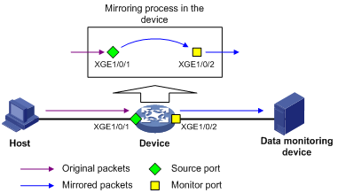
As shown in Figure 80, the source port (Ten-GigabitEthernet 1/0/1) and the monitor port (Ten-GigabitEthernet 1/0/2) reside on the same device. Packets received on Ten-GigabitEthernet 1/0/1 are copied to Ten-GigabitEthernet 1/0/2. Ten-GigabitEthernet 1/0/2 then forwards the packets to the data monitoring device for analysis.
Remote port mirroring
In remote port mirroring, the following conditions exist:
The source device is not directly connected to a data monitoring device.
The source device copies mirrored packets to the destination device, which forwards them to the data monitoring device.
The mirroring sources and the mirroring destination reside on different devices and are in different mirroring groups.
A remote source group is a mirroring group that contains the mirroring sources. A remote destination group is a mirroring group that contains the mirroring destination. Intermediate devices are the devices between the source device and the destination device.
Remote port mirroring includes Layer 2 and Layer 3 remote port mirroring.
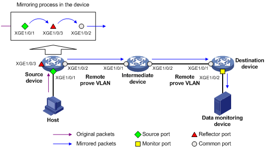
Layer 2 remote port mirroring—The mirroring sources and the mirroring destination are located on different devices on the same Layer 2 network.
Layer 2 remote port mirroring can be implemented when a reflector port or an egress port is available on the source device. The method to use the reflector port and the method to use the egress port are called reflector port method and egress port method, respectively.
Reflector port method—Packets are mirrored as follows:
The source device copies packets received on the mirroring sources to the reflector port.
The reflector port broadcasts the mirrored packets in the remote probe VLAN.
The intermediate devices transmit the mirrored packets to the destination device through the remote probe VLAN.
Upon receiving the mirrored packets, the destination device determines whether the ID of the mirrored packets is the same as the remote probe VLAN ID. If the two VLAN IDs match, the destination device forwards the mirrored packets to the data monitoring device through the monitor port.
Figure 81: Layer 2 remote port mirroring implementation through the reflector port method
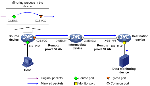
Egress port method—Packets are mirrored as follows:
The source device copies packets received on the mirroring sources to the egress port.
The egress port forwards the mirrored packets to the intermediate devices.
The intermediate devices flood the mirrored packets in the remote probe VLAN and transmit the mirrored packets to the destination device.
Upon receiving the mirrored packets, the destination device determines whether the ID of the mirrored packets is the same as the remote probe VLAN ID. If the two VLAN IDs match, the destination device forwards the mirrored packets to the data monitoring device through the monitor port.
Figure 82: Layer 2 remote port mirroring implementation through the egress port method
In the reflector port method, the reflector port broadcasts mirrored packets in the remote probe VLAN. By assigning a non-source port on the source device to the remote probe VLAN, you can use the reflector port method to implement local port mirroring. The egress port method cannot implement local port mirroring in this way.
To ensure Layer 2 forwarding of the mirrored packets, assign the ports that connect intermediate devices to the source and destination devices to the remote probe VLAN.
To monitor the bidirectional traffic of a source port, disable MAC address learning for the remote probe VLAN on the source, intermediate, and destination devices. For more information about MAC address learning, see Layer 2—LAN Switching Configuration Guide.
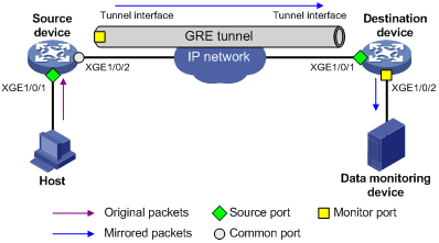
Layer 3 remote port mirroring—The mirroring sources and destination are separated by IP networks.
Layer 3 remote port mirroring is implemented through creating a local mirroring group on both the source device and the destination device. For example, in a network as shown in Figure 83, Layer 3 remote port mirroring works in the following flow:
The source device sends one copy of a packet received on the source port (Ten-GigabitEthernet 1/0/1) to the tunnel interface.
The tunnel interface acts as the monitor port in the local mirroring group created on the source device.
The tunnel interface on the source device forwards the mirrored packet to the tunnel interface on the destination device through the GRE tunnel.
The destination device receives the mirrored packet from the physical interface of the tunnel interface.
The tunnel interface acts as the source port in the local mirroring group created on the destination device.
The physical interface of the tunnel interface sends one copy of the packet to the monitor port (Ten-GigabitEthernet 1/0/2).
Ten-GigabitEthernet 1/0/2 forwards the packet to the data monitoring device.
For more information about GRE tunnels and tunnel interfaces, see Layer 3—IP Services Configuration Guide.
Figure 83: Layer 3 remote port mirroring implementation