Configuration example for NTP broadcast mode with authentication
Network requirements
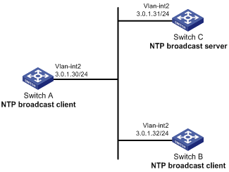
As shown in Figure 43, Switch C functions as the NTP server for multiple devices on different network segments and synchronizes the time among multiple devices. Switch A and Switch B authenticate the reference source.
Configure Switch C's local clock as a reference source, with stratum level 3.
Configure Switch C to operate in broadcast server mode and send broadcast messages from VLAN-interface 2.
Configure Switch A and Switch B to operate in broadcast client mode and receive broadcast messages through VLAN-interface 2.
Enable NTP authentication on Switch A, Switch B, and Switch C.
Figure 43: Network diagram
Configuration procedure
Assign an IP address to each interface, and make sure Switch A, Switch B, and Switch C can reach each other, as shown in Figure 43. (Details not shown.)
Configure Switch A:
# Enable the NTP service.
<SwitchA> system-view
[SwitchA] ntp-service enable
# Enable NTP authentication on Switch A. Configure an NTP authentication key, with the key ID of 88 and key value of 123456. Input the key in plain text, and specify it as a trusted key.
[SwitchA] ntp-service authentication enable
[SwitchA] ntp-service authentication-keyid 88 authentication-mode md5 simple 123456
[SwitchA] ntp-service reliable authentication-keyid 88
# Configure Switch A to operate in NTP broadcast client mode and receive NTP broadcast messages on VLAN-interface 2.
[SwitchA] interface vlan-interface 2
[SwitchA-Vlan-interface2] ntp-service broadcast-client
Configure Switch B:
# Enable the NTP service.
<SwitchB> system-view
[SwitchB] ntp-service enable
# Enable NTP authentication on Switch B. Configure an NTP authentication key, with the key ID of 88 and key value of 123456. Input the key in plain text and specify it as a trusted key.
[SwitchB] ntp-service authentication enable
[SwitchB] ntp-service authentication-keyid 88 authentication-mode md5 simple 123456
[SwitchB] ntp-service reliable authentication-keyid 88
# Configure Switch B to operate in broadcast client mode and receive NTP broadcast messages on VLAN-interface 2.
[SwitchB] interface vlan-interface 2
[SwitchB-Vlan-interface2] ntp-service broadcast-client
Configure Switch C:
# Enable the NTP service.
<SwitchC> system-view
[SwitchC] ntp-service enable
# Specify the local clock as the reference source, with stratum level 3.
[SwitchC] ntp-service refclock-master 3
# Configure Switch C to operate in NTP broadcast server mode and use VLAN-interface 2 to send NTP broadcast packets.
[SwitchC] interface vlan-interface 2
[SwitchC-Vlan-interface2] ntp-service broadcast-server
[SwitchC-Vlan-interface2] quit
Verify the configuration:
NTP authentication is enabled on Switch A and Switch B, but not on Switch C, so Switch A and Switch B cannot synchronize their local clocks to Switch C.
# Verify that Switch B has not synchronized to Switch C.
[SwitchB-Vlan-interface2] display ntp-service status
 Clock status: unsynchronized
 Clock stratum: 16
 Reference clock ID: none
Enable NTP authentication on Switch C:
# Enable NTP authentication on Switch C. Configure an NTP authentication key, with the key ID of 88 and key value of 123456. Input the key in plain text, and specify it as a trusted key.
[SwitchC] ntp-service authentication enable
[SwitchC] ntp-service authentication-keyid 88 authentication-mode md5 simple 123456
[SwitchC] ntp-service reliable authentication-keyid 88
# Specify Switch C as an NTP broadcast server, and associate the key 88 with Switch C.
[SwitchC] interface vlan-interface 2
[SwitchC-Vlan-interface2] ntp-service broadcast-server authentication-keyid 88
Verify the configuration:
# Verify that Switch B has synchronized to Switch C, and the clock stratum level is 4 on Switch B and 3 on Switch C.
[SwitchB-Vlan-interface2] display ntp-service status
 Clock status: synchronized
 Clock stratum: 4
 System peer: 3.0.1.31
 Local mode: bclient
 Reference clock ID: 3.0.1.31
 Leap indicator: 00
 Clock jitter: 0.006683 s
 Stability: 0.000 pps
 Clock precision: 2^-18
 Root delay: 0.00127 ms
 Root dispersion: 2.89877 ms
 Reference time: d0d287a7.3119666f  Sat, Jan  8 2011  6:50:15.191
# Verify that an IPv4 NTP association has been established between Switch B and Switch C.
[SwitchB-Vlan-interface2] display ntp-service sessions
       source          reference       stra reach poll  now offset  delay disper
********************************************************************************
 [1245]3.0.1.31        127.127.1.0        3     3   64   68   -0.0 0.0000    0.0
Notes: 1 source(master),2 source(peer),3 selected,4 candidate,5 configured.
 Total sessions: 1