NTP multicast mode configuration example
Network requirements
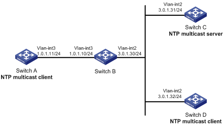
As shown in Figure 40, Switch C functions as the NTP server for multiple devices on different network segments and synchronizes the time among multiple devices.
Configure Switch C's local clock as a reference source, with stratum level 2.
Configure Switch C to operate in multicast server mode and send multicast messages from VLAN-interface 2.
Configure Switch A and Switch D to operate in multicast client mode and receive multicast messages through VLAN-interface 3 and VLAN-interface 2, respectively.
Figure 40: Network diagram
Configuration procedure
Assign an IP address to each interface, and make sure the switches can reach each other, as shown in Figure 40. (Details not shown.)
Configure Switch C:
# Enable the NTP service.
<SwitchC> system-view
[SwitchC] ntp-service enable
# Specify the local clock as the reference source, with stratum level 2.
[SwitchC] ntp-service refclock-master 2
# Configure Switch C to operate in multicast server mode and send multicast messages through VLAN-interface 2.
[SwitchC] interface vlan-interface 2
[SwitchC-Vlan-interface2] ntp-service multicast-server
Configure Switch D:
# Enable the NTP service.
<SwitchD> system-view
[SwitchD] ntp-service enable
# Configure Switch D to operate in multicast client mode and receive multicast messages on VLAN-interface 2.
[SwitchD] interface vlan-interface 2
[SwitchD-Vlan-interface2] ntp-service multicast-client
Verify the configuration:
Switch D and Switch C are on the same subnet, so Switch D can do the following:
Receive the multicast messages from Switch C without being enabled with the multicast functions.
Synchronize to Switch C.
# Verify that Switch D has synchronized to Switch C, and the clock stratum level is 3 on Switch D and 2 on Switch C.
[SwitchD-Vlan-interface2] display ntp-service status
 Clock status: synchronized
 Clock stratum: 3
 System peer: 3.0.1.31
 Local mode: bclient
 Reference clock ID: 3.0.1.31
 Leap indicator: 00
 Clock jitter: 0.044281 s
 Stability: 0.000 pps
 Clock precision: 2^-18
 Root delay: 0.00229 ms
 Root dispersion: 4.12572 ms
 Reference time: d0d289fe.ec43c720  Sat, Jan  8 2011  7:00:14.922
# Verify that an IPv4 NTP association has been established between Switch D and Switch C.
[SwitchD-Vlan-interface2] display ntp-service sessions
       source          reference       stra reach poll  now offset  delay disper
********************************************************************************
 [1245]3.0.1.31        127.127.1.0        2     1   64  519   -0.0 0.0022 4.1257
Notes: 1 source(master),2 source(peer),3 selected,4 candidate,5 configured.
 Total sessions: 1
Configure Switch B:
Because Switch A and Switch C are on different subnets, you must enable the multicast functions on Switch B before Switch A can receive multicast messages from Switch C.
# Enable IP multicast routing and IGMP.
<SwitchB> system-view
[SwitchB] multicast routing
[SwitchB-mrib] quit
[SwitchB] interface vlan-interface 2
[SwitchB-Vlan-interface2] pim dm
[SwitchB-Vlan-interface2] quit
[SwitchB] vlan 3
[SwitchB-vlan3] port ten-gigabitethernet 1/0/1
[SwitchB-vlan3] quit
[SwitchB] interface vlan-interface 3
[SwitchB-Vlan-interface3] igmp enable
[SwitchB-Vlan-interface3] igmp static-group 224.0.1.1
[SwitchB-Vlan-interface3] quit
[SwitchB] igmp-snooping
[SwitchB-igmp-snooping] quit
[SwitchB] interface ten-gigabitethernet 1/0/1
[SwitchB-Ten-GigabitEthernet1/0/1] igmp-snooping static-group 224.0.1.1 vlan 3
Configure Switch A:
# Enable the NTP service.
<SwitchA> system-view
[SwitchA] ntp-service enable
# Configure Switch A to operate in multicast client mode and receive multicast messages on VLAN-interface 3.
[SwitchA] interface vlan-interface 3
[SwitchA-Vlan-interface3] ntp-service multicast-client
Verify the configuration:
# Verify that Switch A has synchronized to Switch C, and the clock stratum level is 3 on Switch A and 2 on Switch C.
[SwitchA-Vlan-interface3] display ntp-service status
 Clock status: synchronized
 Clock stratum: 3
 System peer: 3.0.1.31
 Local mode: bclient
 Reference clock ID: 3.0.1.31
 Leap indicator: 00
 Clock jitter: 0.165741 s
 Stability: 0.000 pps
 Clock precision: 2^-18
 Root delay: 0.00534 ms
 Root dispersion: 4.51282 ms
 Reference time: d0c61289.10b1193f  Wed, Dec 29 2010 20:03:21.065
# Verify that an IPv4 NTP association has been established between Switch A and Switch C.
[SwitchA-Vlan-interface3] display ntp-service sessions
       source          reference       stra reach poll  now offset  delay disper
********************************************************************************
 [1234]3.0.1.31        127.127.1.0        2   247   64  381   -0.0 0.0053 4.5128
Notes: 1 source(master),2 source(peer),3 selected,4 candidate,5 configured.
 Total sessions: 1