DLSw operation configuration example
Network requirements
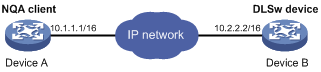
As shown in Figure 19, configure a DLSw operation to test the response time of the DLSw device.
Figure 19: Network diagram
Configuration procedure
# Assign IP addresses to interfaces, as shown in Figure 19. (Details not shown.)
# Configure static routes or a routing protocol to make sure the devices can reach each other. (Details not shown.)
# Create a DLSw operation.
<DeviceA> system-view
[DeviceA] nqa entry admin test1
[DeviceA-nqa-admin-test1] type dlsw
# Specify 10.2.2.2 as the destination IP address.
[DeviceA-nqa-admin-test1-dlsw] destination ip 10.2.2.2
# Enable the saving of history records.
[DeviceA-nqa-admin-test1-dlsw] history-record enable
[DeviceA-nqa-admin-test1-dlsw] quit
# Start the DLSw operation.
[DeviceA] nqa schedule admin test1 start-time now lifetime forever
# After the DLSw operation runs for a period of time, stop the operation.
[DeviceA] undo nqa schedule admin test1
# Display the most recent result of the DLSw operation.
[DeviceA] display nqa result admin test1
NQA entry (admin admin, tag test1) test results:
    Send operation times: 1              Receive response times: 1
    Min/Max/Average round trip time: 19/19/19
    Square-Sum of round trip time: 361
    Last succeeded probe time: 2011-11-22 10:40:27.7
  Extended results:
    Packet loss ratio: 0%
    Failures due to timeout: 0
    Failures due to disconnect: 0
    Failures due to no connection: 0
    Failures due to internal error: 0
    Failures due to other errors: 0
# Display the history records of the DLSw operation.
[DeviceA] display nqa history admin test1
NQA entry (admin admin, tag test1) history records:
  Index      Response     Status           Time
  1          19           Succeeded        2011-11-22 10:40:27.7
The output shows that the response time of the DLSw device is 19 milliseconds.