PVST configuration example
Network requirements
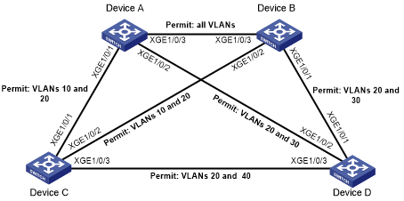
As shown in Figure 34, Device A and Device B work at the distribution layer, and Device C and Device D work at the access layer.
Configure PVST to meet the following requirements:
Packets of a VLAN are forwarded along the spanning trees of the VLAN.
VLAN 10, VLAN 20, and VLAN 30 are terminated on the distribution layer devices, and VLAN 40 is terminated on the access layer devices.
The root bridge of VLAN 10 and VLAN 20 is Device A.
The root bridge of VLAN 30 is Device B.
The root bridge of VLAN 40 is Device C.
Figure 34: Network diagram
Configuration procedure
Configure VLANs and VLAN member ports. (Details not shown.)
Create VLAN 10, VLAN 20, and VLAN 30 on both Device A and Device B.
Create VLAN 10, VLAN 20, and VLAN 40 on Device C.
Create VLAN 20, VLAN 30, and VLAN 40 on Device D.
Configure the ports on these devices as trunk ports and assign them to related VLANs.
Configure Device A:
# Set the spanning tree mode to PVST.
<DeviceA> system-view
[DeviceA] stp mode pvst
# Configure the device as the root bridge of VLAN 10 and VLAN 20.
[DeviceA] stp vlan 10 20 root primary
# Enable the spanning tree feature globally and in VLAN 10, VLAN 20, and VLAN 30.
[DeviceA] stp global enable
[DeviceA] stp vlan 10 20 30 enable
Configure Device B:
# Set the spanning tree mode to PVST.
<DeviceB> system-view
[DeviceB] stp mode pvst
# Configure the device as the root bridge of VLAN 30.
[DeviceB] stp vlan 30 root primary
# Enable the spanning tree feature globally and in VLAN 10, VLAN 20, and VLAN 30.
[DeviceB] stp global enable
[DeviceB] stp vlan 10 20 30 enable
Configure Device C:
# Set the spanning tree mode to PVST.
<DeviceC> system-view
[DeviceC] stp mode pvst
# Configure the device as the root bridge of VLAN 40.
[DeviceC] stp vlan 40 root primary
# Enable the spanning tree feature globally and in VLAN 10, VLAN 20, and VLAN 40.
[DeviceC] stp global enable
[DeviceC] stp vlan 10 20 40 enable
Configure Device D:
# Set the spanning tree mode to PVST.
<DeviceD> system-view
[DeviceD] stp mode pvst
# Enable the spanning tree feature globally and in VLAN 20, VLAN 30, and VLAN 40.
[DeviceD] stp global enable
[DeviceD] stp vlan 20 30 40 enable
Verifying the configuration
When the network is stable, use the display stp brief command to display brief spanning tree information on each device.
# Display brief spanning tree information on Device A.
[DeviceA] display stp brief
 VLAN ID     Port                                      Role  STP State     Protection
 10          Ten-GigabitEthernet1/0/1                  DESI  FORWARDING    NONE
 10          Ten-GigabitEthernet1/0/3                  DESI  FORWARDING    NONE
 20          Ten-GigabitEthernet1/0/1                  DESI  FORWARDING    NONE
 20          Ten-GigabitEthernet1/0/2                  DESI  FORWARDING    NONE
 20          Ten-GigabitEthernet1/0/3                  DESI  FORWARDING    NONE
 30          Ten-GigabitEthernet1/0/2                  DESI  FORWARDING    NONE
 30          Ten-GigabitEthernet1/0/3                  ROOT  FORWARDING    NONE
# Display brief spanning tree information on Device B.
[DeviceB] display stp brief
 VLAN ID     Port                                      Role  STP State     Protection
 10          Ten-GigabitEthernet1/0/2                  DESI  FORWARDING    NONE
 10          Ten-GigabitEthernet1/0/3                  ROOT  FORWARDING    NONE
 20          Ten-GigabitEthernet1/0/1                  DESI  FORWARDING    NONE
 20          Ten-GigabitEthernet1/0/2                  DESI  FORWARDING    NONE
 20          Ten-GigabitEthernet1/0/3                  ROOT  FORWARDING    NONE
 30          Ten-GigabitEthernet1/0/1                  DESI  FORWARDING    NONE
 30          Ten-GigabitEthernet1/0/3                  DESI  FORWARDING    NONE
# Display brief spanning tree information on Device C.
[DeviceC] display stp brief
 VLAN ID     Port                                      Role  STP State     Protection
 10          Ten-GigabitEthernet1/0/1                  ROOT  FORWARDING    NONE
 10          Ten-GigabitEthernet1/0/2                  ALTE  DISCARDING    NONE
 20          Ten-GigabitEthernet1/0/1                  ROOT  FORWARDING    NONE
 20          Ten-GigabitEthernet1/0/2                  ALTE  DISCARDING    NONE
 20          Ten-GigabitEthernet1/0/3                  DESI  FORWARDING    NONE
 40          Ten-GigabitEthernet1/0/3                  DESI  FORWARDING    NONE
# Display brief spanning tree information on Device D.
[DeviceD] display stp brief
 VLAN ID     Port                                      Role  STP State     Protection
 20          Ten-GigabitEthernet1/0/1                  ALTE  DISCARDING    NONE
 20          Ten-GigabitEthernet1/0/2                  ROOT  FORWARDING    NONE
 20          Ten-GigabitEthernet1/0/3                  ALTE  DISCARDING    NONE
 30          Ten-GigabitEthernet1/0/1                  ROOT  FORWARDING    NONE
 30          Ten-GigabitEthernet1/0/2                  ALTE  DISCARDING    NONE
 40          Ten-GigabitEthernet1/0/3                  ROOT  FORWARDING    NONE
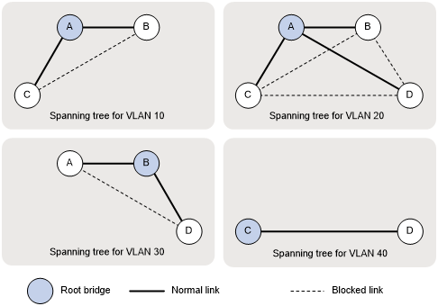
Based on the output, you can draw a topology for each VLAN spanning tree, as shown in Figure 35.
Figure 35: VLAN spanning tree topologies