Example for configuring a remote CCC connection
Network requirements
The CEs are connected to the PEs through VLAN interfaces.
Create a remote CCC connection, so CE 1 and CE 2 can exchange Layer 2 packets across the backbone network.
Figure 56: Network diagram
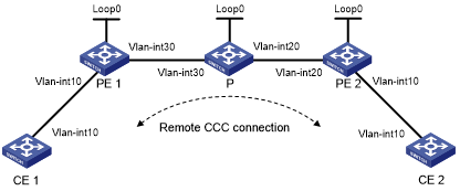
Device | Interface | IP address | Device | Interface | IP address |
CE 1 | Vlan-int10 | 100.1.1.1/24 | CE 2 | Vlan-int10 | 100.1.1.2/24 |
PE 1 | Loop0 | 10.0.0.1/32 | P | Loop0 | 10.0.0.2/32 |
Vlan-int30 | 10.1.1.1/24 | Vlan-int20 | 10.2.2.2/24 | ||
PE 2 | Loop0 | 10.0.0.3/32 | Vlan-int30 | 10.1.1.2/24 | |
Vlan-int20 | 10.2.2.1/24 |
Configuration considerations
The following steps are required:
Create remote CCC connections on the PEs. No static LSP is required on the PEs.
Configure two static LSPs on the P device for packets to be transferred in both directions.
Configuration procedure
Configure CE 1:
# Configure an IP address for the interface connected to PE 1.
<Sysname> system-view
[Sysname] sysname CE1
[CE1] interface vlan-interface 10
[CE1-Vlan-interface10] ip address 100.1.1.1 24
Configure PE 1:
# Configure the LSR ID and enable MPLS globally.
<Sysname> system-view
[Sysname] sysname PE1
[PE1] interface loopback 0
[PE1-LoopBack0] ip address 10.0.0.1 32
[PE1-LoopBack0] quit
[PE1] mpls lsr-id 10.0.0.1
[PE1] mpls
[PE1-mpls] quit
# Enable L2VPN and MPLS L2VPN.
[PE1] l2vpn
[PE1-l2vpn] mpls l2vpn
[PE1-l2vpn] quit
# Configure interface VLAN-interface 10.
[PE2] interface vlan-interface 10
[PE2-Vlan-interface10] quit
# Configure interface VLAN-interface 30 and enable MPLS.
[PE1] interface vlan-interface 30
[PE1-Vlan-interface30] ip address 10.1.1.1 24
[PE1-Vlan-interface30] mpls
[PE1-Vlan-interface30] quit
# Create a remote connection from CE 1 to CE 2, using the interface connected to CE 1 as the incoming interface and that connecting the P device as the outgoing interface, setting the incoming label to 100 and the outgoing label to 200.
[PE1] ccc ce1-ce2 interface vlan-interface 10 in-label 100 out-label 200 nexthop 10.1.1.2
Configure the P device:
# Configure the LSR ID and enable MPLS globally.
<Sysname> system-view
[Sysname] sysname P
[P] interface loopback 0
[P-LoopBack0] ip address 10.0.0.2 32
[P-LoopBack0] quit
[P] mpls lsr-id 10.0.0.2
[P] mpls
[P-mpls] quit
# Configure interface VLAN-interface 30 and enable MPLS.
[P] interface vlan-interface 30
[P-Vlan-interface30] ip address 10.1.1.2 24
[P-Vlan-interface30] mpls
[P-Vlan-interface30] quit
# Configure interface VLAN-interface 20 and enable MPLS.
[P] interface vlan-interface 20
[P-Vlan-interface20] ip address 10.2.2.2 24
[P-Vlan-interface20] mpls
[P-Vlan-interface20] quit
# Create a static LSP for forwarding packets from PE 1 to PE 2.
[P] static-lsp transit pe1_pe2 incoming-interface vlan-interface 30 in-label 200 nexthop 10.2.2.1 out-label 201
# Create a static LSP for forwarding packets from PE 2 to PE 1.
[P] static-lsp transit pe2_pe1 incoming-interface vlan-interface 20 in-label 101 nexthop 10.1.1.1 out-label 100
Configure PE 2:
# Configure the LSR ID and enable MPLS globally.
<Sysname> system-view
[Sysname] sysname PE2
[PE2] interface loopback 0
[PE2-LoopBack0] ip address 10.0.0.3 32
[PE2-LoopBack0] quit
[PE2] mpls lsr-id 10.0.0.3
[PE2] mpls
[PE2-mpls] quit
# Enable L2VPN and MPLS L2VPN.
[PE2] l2vpn
[PE2-l2vpn] mpls l2vpn
[PE2-l2vpn] quit
# Configure interface VLAN-interface 10.
[PE2] interface vlan-interface 10
[PE2-Vlan-interface10] quit
# Configure interface VLAN-interface 20 and enable MPLS.
[PE2] interface vlan-interface 20
[PE2-Vlan-interface20] ip address 10.2.2.1 24
[PE2-Vlan-interface20] mpls
[PE2-Vlan-interface20] quit
# Create a remote connection from CE 2 to CE 1, using the interface connected to CE 2 as the incoming interface and that connecting the P device as the outgoing interface, setting the incoming label to 201 and the outgoing label to 101.
[PE2] ccc ce2-ce1 interface vlan-interface 10 in-label 201 out-label 101 nexthop 10.2.2.2
Configure CE 2:
# Configure an IP address for the interface connected to PE 2.
<Sysname> system-view
[Sysname] sysname CE2
[CE2] interface vlan-interface 10
[CE2-Vlan-interface10] ip address 100.1.1.2 24
Verify the configuration:
# Display CCC connection information on PE 1. The output shows that a remote CCC connection has been established.
[PE1] display ccc
    Total  ccc vc          : 1
    Local  ccc vc          : 0,  0 up
    Remote ccc vc          : 1,  1 up
 ***Name                   : ce1-ce2
    Type                   : remote
    State                  : up
    Intf                   : Vlan-interface10 (up)
    In-label               : 100
    Out-label              : 200
    Nexthop                : 10.1.1.2
# Ping CE 2 from CE 1. The output shows that CE 1 and CE 2 can ping each other.
[CE1] ping 100.1.1.2
  PING 100.1.1.2: 56  data bytes, press CTRL_C to break
    Reply from 100.1.1.2: bytes=56 Sequence=1 ttl=255 time=180 ms
    Reply from 100.1.1.2: bytes=56 Sequence=2 ttl=255 time=60 ms
    Reply from 100.1.1.2: bytes=56 Sequence=3 ttl=255 time=10 ms
    Reply from 100.1.1.2: bytes=56 Sequence=4 ttl=255 time=70 ms
    Reply from 100.1.1.2: bytes=56 Sequence=5 ttl=255 time=60 ms
  --- 100.1.1.2 ping statistics ---
    5 packet(s) transmitted
    5 packet(s) received
    0.00% packet loss
    round-trip min/avg/max = 10/76/180 ms