VRRP with multiple VLANs configuration example
Network requirements
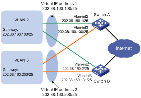
Hosts in VLAN 2 use 202.38.160.100/25 as their default gateway and hosts in VLAN 3 use 202.38.160.200/25 as their default gateway.
Switch A and Switch B belong to both VRRP group 1 and VRRP group 2. The virtual IP address of VRRP group 1 is 202.38.160.100/25, and that of VRRP group 2 is 202.38.160.200/25.
In VRRP group 1, Switch A has a higher priority than Switch B. In VRRP group 2, Switch B has a higher priority than Switch A. In this case, hosts in VLAN 2 and VLAN 3 can communicate with external networks through Switch A and Switch B, respectively, and when Switch A or Switch B fails, the hosts can use the other switch to communicate with external networks to avoid communication interruption.
Figure 41: Network diagram
Configuration procedure
Configure Switch A:
# Configure VLAN 2.
<SwitchA> system-view
[SwitchA] vlan 2
[SwitchA-vlan2] port gigabitethernet 1/0/5
[SwitchA-vlan2] quit
[SwitchA] interface vlan-interface 2
[SwitchA-Vlan-interface2] ip address 202.38.160.1 255.255.255.128
# Create a VRRP group 1 and set its virtual IP address to 202.38.160.100.
[SwitchA-Vlan-interface2] vrrp vrid 1 virtual-ip 202.38.160.100
# Configure the priority of Switch A in VRRP group 1 as 110, which is higher than that of Switch B (100), so that Switch A can become the master in VRRP group 1.
[SwitchA-Vlan-interface2] vrrp vrid 1 priority 110
[SwitchA-Vlan-interface2] quit
# Configure VLAN 3.
[SwitchA] vlan 3
[SwitchA-vlan3] port gigabitethernet 1/0/6
[SwitchA-vlan3] quit
[SwitchA] interface vlan-interface 3
[SwitchA-Vlan-interface3] ip address 202.38.160.130 255.255.255.128
# Create a VRRP group 2 and set its virtual IP address to 202.38.160.200.
[SwitchA-Vlan-interface3] vrrp vrid 2 virtual-ip 202.38.160.200
Configure Switch B:
# Configure VLAN 2.
<SwitchB> system-view
[SwitchB] vlan 2
[SwitchB-vlan2] port gigabitethernet 1/0/5
[SwitchB-vlan2] quit
[SwitchB] interface vlan-interface 2
[SwitchB-Vlan-interface2] ip address 202.38.160.2 255.255.255.128
# Create a VRRP group 1 and set its virtual IP address to 202.38.160.100.
[SwitchB-Vlan-interface2] vrrp vrid 1 virtual-ip 202.38.160.100
[SwitchB-Vlan-interface2] quit
# Configure VLAN 3.
[SwitchB] vlan 3
[SwitchB-vlan3] port gigabitethernet 1/0/6
[SwitchB-vlan3] quit
[SwitchB] interface vlan-interface 3
[SwitchB-Vlan-interface3] ip address 202.38.160.131 255.255.255.128
# Create a VRRP group 2 and set its virtual IP address to 202.38.160.200.
[SwitchB-Vlan-interface3] vrrp vrid 2 virtual-ip 202.38.160.200
# Configure the priority of Switch B in VRRP group 2 to 110, which is higher than that of Switch A (100), so that Switch B can become the master in VRRP group 2.
[SwitchB-Vlan-interface3] vrrp vrid 2 priority 110
Verify the configuration:
To verify your configuration, use the display vrrp verbose command.
# Display the detailed information about the VRRP group on Switch A.
[SwitchA-Vlan-interface3] display vrrp verbose
 IPv4 Standby Information:
     Run Mode       : Standard
     Run Method     : Virtual MAC
 Total number of virtual routers : 2
   Interface Vlan-interface2
     VRID           : 1               Adver Timer  : 1
     Admin Status   : Up              State        : Master
     Config Pri     : 110             Running Pri  : 110
     Preempt Mode   : Yes             Delay Time   : 0
     Auth Type      : None
     Virtual IP     : 202.38.160.100
     Virtual MAC    : 0000-5e00-0101
     Master IP      : 202.38.160.1
   Interface Vlan-interface3
     VRID           : 2               Adver Timer  : 1
     Admin Status   : Up              State        : Backup
     Config Pri     : 100             Running Pri  : 100
     Preempt Mode   : Yes             Delay Time   : 0
     Become Master  : 2200ms left
     Auth Type      : None
     Virtual IP     : 202.38.160.200
     Master IP      : 202.38.160.131
# Display the detailed information about the VRRP group on Switch B.
[SwitchB-Vlan-interface3] display vrrp verbose
 IPv4 Standby Information:
     Run Mode       : Standard
     Run Method     : Virtual MAC
 Total number of virtual routers : 2
   Interface Vlan-interface2
     VRID           : 1               Adver Timer  : 1
     Admin Status   : Up              State        : Backup
     Config Pri     : 100             Running Pri  : 100
     Preempt Mode   : Yes             Delay Time   : 0
     Become Master  : 2200ms left
     Auth Type      : None
     Virtual IP     : 202.38.160.100
     Master IP      : 202.38.160.1
   Interface Vlan-interface3
     VRID           : 2               Adver Timer  : 1
     Admin Status   : Up              State        : Master
     Config Pri     : 110             Running Pri  : 110
     Preempt Mode   : Yes             Delay Time   : 0
     Auth Type      : None
     Virtual IP     : 202.38.160.200
     Virtual MAC    : 0000-5e00-0102
     Master IP      : 202.38.160.131
The output shows that in VRRP group 1 Switch A is the master, Switch B is the backup and hosts with the default gateway of 202.38.160.100/25 accesses the Internet through Switch A; in VRRP group 2 Switch A is the backup, Switch B is the master and hosts with the default gateway of 202.38.160.200/25 accesses the Internet through Switch B.