GRE encapsulation and de-encapsulation processes
Figure 96: X protocol networks interconnected through a GRE tunnel
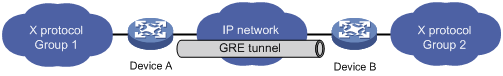
The following sections uses Figure 96 to describe how an X protocol packet traverses the IP network through a GRE tunnel.
Encapsulation process
After receiving an X protocol packet through the interface connected to Group 1, Device A submits it to the X protocol for processing.
The X protocol checks the destination address field in the packet header to determine how to route the packet.
If the packet must be tunneled to reach its destination, Device A sends it to the tunnel interface.
Upon receipt of the packet, the tunnel interface encapsulates it in a GRE packet. Then, the system encapsulates the packet in an IP packet and forwards the IP packet based on its destination address and the routing table.
![[NOTE: ]](images/note.png)
NOTE:
The switch cannot forward encapsulated packets directly according to the destination address and the routing table. On the switch, encapsulated packets are first sent to the service loopback interface and then forwarded by the service loopback interface back to the forwarding module, which forwards the packets at Layer 3.
De-encapsulation process
De-encapsulation is the reverse of the encapsulation process:
Upon receiving an IP packet from the tunnel interface, Device B checks the destination address.
If the destination is itself and the protocol number in the IP header is 47 (the protocol number for GRE), Device B strips off the IP header of the packet and submits the resulting packet to the GRE protocol.
The GRE protocol checks the key, checksum and sequence number in the packet, and then strips off the GRE header and submits the payload to the X protocol for forwarding.
NOTE:
Encapsulation and de-encapsulation processes on both ends of the GRE tunnel and the resulting increase in data volumes will degrade the forwarding efficiency of a GRE-enabled device to some extent.